Demonstration of the E-Cat QX - 24 November - Summary thread
-
-
There are two methods to ignite the flame in a cigarette lighter.
One of them utilizes a piezoelectric high voltage generator that makes a spark in the fuel-air mixture to be ignited.
A spark is nothing but a plasma like in the Rossi QuackX.
Perhaps you should look for nuclear radiation from piezoelectric cigarette lighters being lit?
You could win the IG Nobel Price!
-

On a more serious note, that provisional patent only claims that 50-100 kV voltages are being used, not how they're generated.
One could also argue that at 3-6 bar of pressure electrons won't be accelerated as claimed, so it's wrong or misleading information anyway.
One more issue that just occurred to me. There is THREE QX reactors and only one controller input signal. So it looks like the High voltage activation pulse is driving all three QX reactors in parallel. And that fractal input sine wave thing is also affecting all three reactors identically. The QX is a dumb slave to the controller.
-

... And that fractal input sine wave thing ...
I am trying to parse this. Do you mean to refer here to an input that is a fractal sine wave?
What is a fractal sine wave?
-
Something similar to this:
https://math.stackexchange.com…sine-wave/1484424#1484424
I think I used the term first before in this thread: I really only meant it as an alternative wording to the patented "superwave" (by Dardik et al).
-
Plainly not a superwave, its just the result of the product of 2 sine waves, with the lower frequency being full wave rectified (absolute value).
-

Plainly not a superwave, its just the result of the product of 2 sine waves, with the lower frequency being full wave rectified (absolute value).
I thought I saw at least 3 in this screenshot; I tried to replicate the shape, albeit not getting a very close match
-
My knowledge in electronics is pretty basic, as probably is that of many other people reading this forum: what is happening in this video exactly? Is the probe measuring a DC offset over the AC signal when put in DC mode?
Please see my post #417 Questioning Scope coupling on page 14
ALL DSOs display only the AC component of a signal when in AC coupling mode.
When in DC coupling mode, they display the combined AC and DC signal.
This is about input coupling.
You might want to read up about Trigger Coupling
Just as you can select either AC or DC coupling for the vertical system, you can choose the kind of coupling for the trigger signal.
This is more relevant to handheld meters.
-
I think Mats Lewan also had a digital multimeter, I wonder if he verified the oscilloscope peak readings with it on the 1 Ohm resistor when the QX was operating.
-
-
-
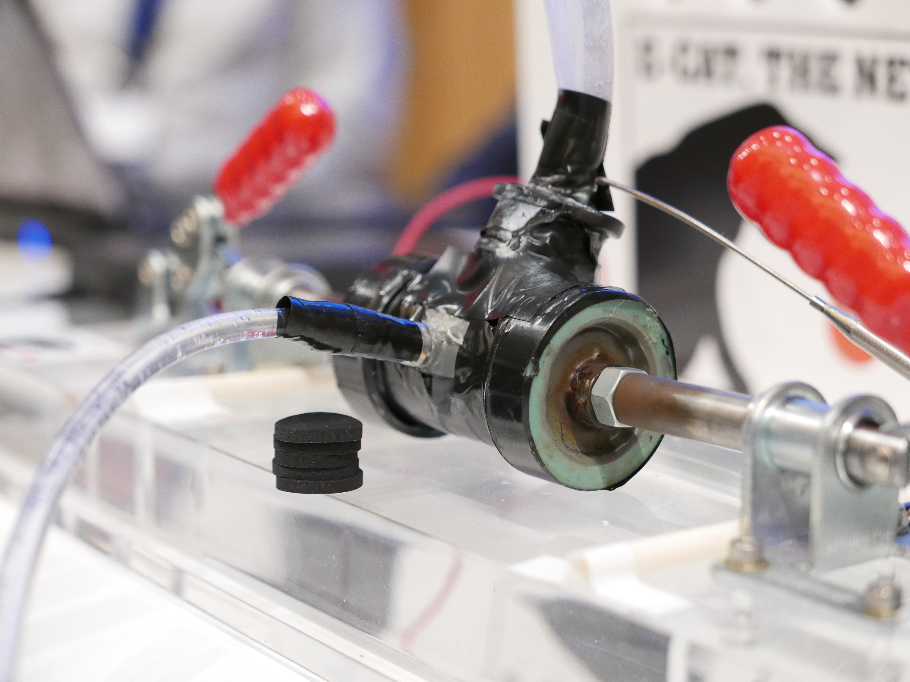
Here, from Siffer's execrable web site, is a really sharp, closeup photo of Rossi's kludge. I can't get past the idea of wrapping a nuclear fission reactor in what Alan calls duct tape. But it's not even as good as duct tape. It's the cheapest possible vinyl electrical tape that turns into a mushy sticky mess at temperatures around those of boiling water. The end caps look as if they were made from the wheels on a child's skate or toy. The body is probably a "T" fitting intended for garden irrigation tubing. His supporters should really buy a few machine tools for Rossi and not allow him into junk or hardware stores. Several people talked about how he is looking for a very dumb inventor. I'd make that a very EXTREMELY dumb investor.
http://www.sifferkoll.se/siffe…oads/2017/11/L1010537.jpg
If the web site allows hot links, you will see the actual photo below:
-
@Mary Yugo ,
That is a great photo by Sifferkol. I can see that the cinch nut has been removed, and just the (new) bolt screwed into the clamp Rod end. That cap will be pressed into the Orbit irrigation fitting. It seems to have some epoxy or a weld joining a bushing or metal sleeve to the portion pressed into the coupler.
You can also see where the coupler was dropped or struck with something after assembly, from a dent going through the tape on the irrigation coupler end.
-
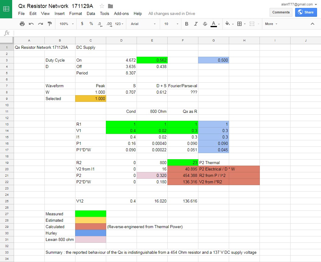
OK .. I got the on/off duty cycles (0.56 on 0.44 off, 8.3 sec period) from the video above. (Thx). The on/off period is too short to see if there is the exponential rise/fall of output.
The waveform is complex, so I analyzed it with
a) DC : the reported behaviour of the Qx is indistinguishable from a 454 Ohm resistor and a 137 V DC supply voltageand
b) DC + SINE : the reported behaviour of the Qx is indistinguishable from a 1212 Ohm resistor and a 364 V DC+ SINE supply voltage
Edit : I just spotted a mistake here ... I applied the waveform correction facto for VOLTAGE .. it needs to be SQUARED for Power. (For the DC case the factor is 1)
Corrected in b) above
Spreadsheets for DC Supply and DC + SINE (corrected)
Screenshots:ps : The use of the 1 ohm resistor for determining the COP is meaningless.
pps : Without a measurement of the supply voltage the test is NULL. -
MY: "The body is probably a "T" fitting intended for garden irrigation tubing"
Looking at previous photographs, earlier, more primitive versions of this paradigm-shifting device did not incorporate the crucial electrician's tape shielding of the primary manifold and therefore revealed its specific nature: a 1-inch Blu-Lock lawn sprinkler fitting (which, to be fair to Rossi, is a high-quality PVC component.)
-
I thought I saw at least 3 in this screenshot; I tried to replicate the shape, albeit not getting a very close match
Why isn't it just a sum of sines ... something like this (500Hz + 410 Hz)
-
Fairly close. Same amplitude?
-

Fairly close. Same amplitude?
Me?
Yes same amplitude. The most simple-minded set of signals you could imagine. You can play around at https://academo.org/demos/wave-interference-beat-frequency/
-

t is clear that the clamp rods are very nearly fully extended. And rusty. The bolt head, just beyond the more clean cinch nut at the end of the rod looks really rusty.
That rust also caught my eyes earlier, and it reminds me of one phenomenon namely oxidation. When you apply high voltage spark, it generates also ozone, and ozone causes fast oxidation. Looking at rust in Sifferkolls pic above it seems thicker closer to reactor.
But question is why shouldn':t QX reactor be sealed, or if it has crystal glass chamber, then UV-C passes it forming ozone outside the reactor.
Did anyone (ping Alan Smith Mats Lewan ) smell ozone during test run? -
I think this is close. f1 * ABS(f2) with f1 being about 8.6666 times f2.