1. Show me the proof of that? I was asked a question, and said I didn't KNOW whether they were "HVAC Engineering" or "Scientific" accurate.
2. For DIFFERENTIAL analysis. I've given TWO references saying they OVER-READ for TURBULENT FLOW.
My Chart 4 shows that R20 doesn't follow "fan law" (see next post for some comments) where R19 DOES.
Mizuno doesn't account for fan-law temperature dependence

Mizuno Airflow Calorimetry
- Alan Fletcher
- Closed
-
-
Show me the proof of that? I was asked a question, and said I didn't KNOW whether they were "HVAC Engineering" or "Scientific" accurate.
You have no idea..
and yet you have a concern
what a joke!
Its your CONCERN. you substantiate it.
or shut up
Easy Tiger!! Alan.
-
I've given you substantial references to this. You obviously didn't (read or) understand them.
In pharmaceutical terms it would be a black-box warning :
WARNING : DO NOT USE HOT-WIRE ANEMOMETERS FOR QUANTITATIVE MEASUREMENTS IN TURBULENT FLOWS
https://www.trutechtools.com/M…re-Anemometer_c_1001.htmlMeasuring Airflow With a Hot Wire Anemometer
The principal of a hot wire anemometer is based on a heated element from which heat is extracted by the colder impact airflow. The temperature of the hot wire is kept constant via a regulating switch, and the current (amp draw measured internally) is directly proportional to the air velocity. When using a hot wire in turbulent air streams the measured results can be impacted by turbulent airflow striking the measurement sensor from multiple directions. This could indicate a higher measured value than a vane probe. This characteristic is typically prevalent in ducts where turbulent airflow can occur even at very low velocities.
Measurement Location and Selection
All measurements should be made in a straight section of duct if possible. In an ideal location the duct will have a minimum of 10 diameters before the measuring spot and at least 4 diameters after before making a transition of turn. The airflow should not be inferred by dampers.
Hot wires are calibrated to a specific air density and either require the density to be input to the meter or a correction to be made. Many are calibrated to standard air which is 68F 0%Rh and 29.92mmhg. Consult the manufacturer. Hot wires are best suited for low velocity measurements at or near standard air conditions. Care must be used when measuring conditioned and turbulent air. Hot wires are not recommended for air velocities exceeding 2000 FPM unless they are specifically designed for that purpose. Heavy duty models are available that can measure in excess of 6000 FPM.
-
-
I see a transition from a rectangular duct to a circular duct in ... 2 diameters?
-
And : http://www.lth.se/fileadmin/ht…211/lab2b-pm-Eng-2009.pdf
As a general rule-of-thumb, conventional hot wire anemometry should not be used if the
local turbulence intensity is higher than about 35%, at least not for quantitative purposes.
Apart from the mix-up of velocity components (cross-talk), it is evident that a hot wire
can not distinguish between what is forward and backward, it behaves like a rectifier.
(Turbulence intensity is based on the transition from laminar to turbulent flow. Others have reported that the outlet is well into the turbulent flow domain )
See equations 18-19 :The relative error increases quadratically with Tu. For Tu = 10% and H = 1.05, K = 0.20
the systematic error becomes +0.6%; +2.3% for Tu = 20%. Thus, to avoid excessive
systematic errors, it is essential to have low enough turbulence intensities. During velocity
calibrations, the rule-of-thumb is to have Tu < 5%, preferably Tu < 2%.
The relative error in using the approximations ve(t) = u(t) and q ....
instead directly proportional to the turbulence intensity. For Tu = 10%, with H and K
as above, the absolute value of the relative error is less than 3%. -
conventional hot wire anemometry should not be used if the
local turbulence intensity is higher than about 35%, at least not for quantitative purposesdefine turbulent intensity.. first things first... you have no idea".
You need to do an effective google search and not mouth off from a few cherrypicks.
Thesensorofchoiceformanydecadesinwindtunnel experiments and atmospheric boundary layer studies is the hot-wire anemometer (HWA). State-of-the-art sensors for high-resolution turbulence measurements have a bandwidth up to 100 kHz and are, therefore, suitable for turbulence measurements well within the dissipation range. High-resolution measurements with hot wires in the atmosphere have been made, for example, with a sensor package carried by a tethered balloon (Muschinski et al. 2001) or based on a tower (Shaw and Oncley 2001). However, even though the application of hot wires for measurements in two-phase flows is discussed in textbooks (e.g., Bruun 1995; Goldstein 1996), measurementswithHWAinthecloudyatmosphereare rare.
-
Recommendations (using Mizuno's fan) :
Make the outlet tube 15 diameters long, and measure 4 diameters from the outlet.
Use the RPM counter (unused yellow wire) rather than watts, so that the results are linear (rather than squared).Correct the results for temperature.
-

define turbulent intensity..
Equations 18-19 above, -
In pharmaceutical terms it would be a black-box warning :
WARNING : DO NOT USE HOT-WIRE ANEMOMETERS FOR QUANTITATIVE MEASUREMENTS IN TURBULENT FLOWS
A whole lot of engineering patients must have DIED during hotwire anemometry.
For example..
Ricardo Mejia-Alvarez and Hussam Hikmat Jabbar, Department of Mechanical Engineering, Michigan State University, East Lansing, MI
""Turbulent flows exhibit very high frequency fluctuations that require instruments with high time-resolution for their appropriate characterization. Hot-wire anemometers have a short enough time-response to fulfill this requirement. The purpose of this experiment is to demonstrate the use of hot-wire anemometry to characterize a turbulent jet.
-
AS I said before : Hot-wires and IR are great for DIFFERENTIAL analysis.
But *NOT* for quantitative. -
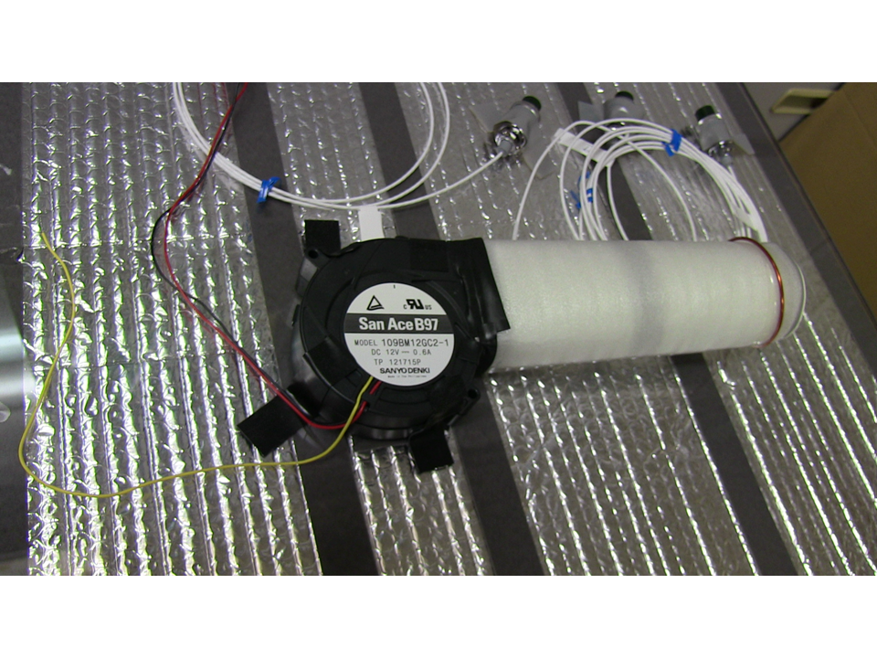
MIZUNO REPLICATION AND MATERIALS ONLY
Details on the outlet pipe. -
-
Since the Reynolds number is proportional to the diameter of a tube, you can convert the turbulent flow in a tube to a laminar flow by stacking small tubes in the large tube (Or have an insert with many small, long holes)
The smaller diameters can bring down the Reynolds number in each sub tube to a value low enough that at the output of the insert, the flow in each sub tube is laminar.
Puting a hot wire anemometer near the output will then enable an accurate reading.
Using this technique in mass flow controllers we found that mass flow could be accurate quantative measured and that the curve was following the physical laws and as a result only a three point calibration of the curve was needed. This while many competing mass flow meters had problems with turbulance and thus needed multipoint calibrations (even up to 10 points)
While i was not involved in the above physical design and have the above only by statements from others involved, I reviewed the electronics used with the mass flow meter/controller.
-

Using this technique in mass flow controllers we found that mass flow could be accurate quantative measured
So you are replicators should use multiple small tubes to convert the flow to laminar..
to avoid turbulent flow..
was this with gas flows or liquid flows... was it viscous fluid
I just wonder why we never used this solution in gas flows..
How many small tubes would be need to convert the 5m/s flow to laminar in the 6.6 cm tube,,
three? at 120 degrees
or using a larger tube...
Laminar flow will probably be down in the 2m/s range which will require an increased pipe diameter(for one) by a factor of sqrt(5/2) ..
Eihter way.. multiple small tubes or one larger one..
Doable.. but clumsy.. the best thing to do is establish by measurement where the turbulent flow is a stable profile.
not too close to the fan blade.. which is what I would have done ... and which I assume Mizuno did
He said it was basic physics.. which it is.. which is why this thread is so pointless
-
Display More
Recommendations (using Mizuno's fan) :
Make the outlet tube 15 diameters long, and measure 4 diameters from the outlet.
Use the RPM counter (unused yellow wire) rather than watts, so that the results are linear (rather than squared).Correct the results for temperature.
In addition, in that case, you can assume for the velocities and dimensions used here an average airflow of approximately 20% lower than the centre of pipe measured velocity multiplied by the cross sectional area, due to velocity profile over pipe cross-section. That assumes teh average velocity t centre of pipe is correctly measured.
-
Doable.. but clumsy.. the best thing to do is establish by measurement where the turbulent flow is a stable profile.
not too close to the fan blade.. which is what I would have done ... and which I assume Mizuno did
He said it was basic physics.. which it is.. which is why this thread is so pointless
I don't think that makes sense (turbulence is not stable directionally or temporally, and the direction changes make hot wire measurement inaccurate for overall airflow): but even if it does: it is a big assumption!
-
I found that one too. RB says that many people use HWAs in turbulent flows. True. But, from all the refs I have found, they use HWAs to measure the amount and frequency of the turbulence, not the overall airflow. For the reasons that are pretty obvious.
-
WARNING : DO NOT USE HOT-WIRE ANEMOMETERS FOR QUANTITATIVE MEASUREMENTS IN TURBULENT FLOWS
That can't be true. That's what anemometers are for. Look at the specifications for the anemometer. It says it works at flow rates and temperatures far above these, which have to be turbulent. Furthermore, this anemometer was recently compared to another, both placed in this calorimeter. They got nearly the same answer. The other one was a vane anemometer and it got a slightly higher reading. Your reference which says that when turbulent flows are a problem, striking the hot wire from different angles, it produces a higher reading than a vane anemometer, so evidently that problem is not happening.
Also, the low power calibrations balance very closely to input, and they never exceed input, so obviously the calorimetry is working.
I suggest you use an anemometer for a while in varying circumstances. Change your test until you get a uniform flow rate at all points across the outlet. That will be a turbulent flow. Then do various tests to confirm the flow rate is correct -- which I am sure it will be with any digital anemometer. You can test this with smoke, or by comparing it to another anemometer, by looking at the blower specifications, or by doing calorimetry.
-
It says it works at flow rates and temperatures far above these, which have to be turbulent.
It does work, perfectly. However what it calculated is not what you need to determine average airflow.
Furthermore, this anemometer was recently compared to another, both placed in this calorimeter. They got nearly the same answer. The other one was a vane anemometer and it got a slightly higher reading. Your reference which says that when turbulent flows are a problem, striking the hot wire from different angles, it produces a higher reading than a vane anemometer, so evidently that problem is not happening.
The problem here is that a vane anenometer would occupy much of the pipe and will not read accurately due to the adjacent walls, so I don't think we can know much from this.