magicsound MFMP
  • Male
  • from Santa Cruz, California USA (UTC -8)
  • Member since Jul 19th 2015
  • Last Activity:

Posts by magicsound

    Here's the schematic with a legend (from the text) added.


    A phosphor screen (or active catalyst?) is described by items 33 and 34 (not in the legend):

    33-Using alloys of gallium, indium, phosphorus, arsenic, germanium, gold, bismuth to form a layered fence around the plasma

    34 - layer of alloy described in symbol 33


    I found this patent today, interesting in that the USPTO now lists Frank Gordon's patent under 'similar devices.

    Good find Alan. The inventor Phillip E. Ohmart was active in the field of nuclear and industrial instrumentation. He apparently passed away in 1964 at age 48, just as his patent was granted. His company Ohmart Corp was then acquired by the German company VEGA Grieshaber KG, still very much in business. Tucked away on their web site is a table of dielectric constants, the most comprehensive I've ever seen: https://www.vega.com/-/media/p…electric_constants_en.pdf

    This is somewhat at odds with Daniel_G's reports of working with Mizuno meshes over the past year.

    Daniel hasn't offered to collaborate or share materials, designs, or data - other than his sparse description of the "furnace". If he wants to contribute to this discussion, I for one would welcome it and he knows where we are.

    @Bruce_H Heat conduction between the mesh and the reactor shell isn't well-controlled, because the mesh isn't very flat or rigid, and is 3-6 layers after rolling it up.


    Regarding internal vs external heat, advice from both Mizuno and me356 is that the reaction is much more likely with internal heating. It's possible that IR irradiation is an important trigger, as well as a thermal gradient and the resulting gas flux through the mesh. I did try internal heat with a cartridge in the thermowell, but it wasn't capable of reaching the temperature needed due to the thin wall of the tubing. So a new cell end flange with power feed-throughs and internal heater coil is the plan. Just not this week....

    me356 Wow, that mesh looks gnarly, as we say here in Surf City. I understand where you're going with the new reactor design. Better thermal coupling makes tight control possible, and more TCs always helps understanding a complex system. Don't neglect the need for calibration in your design process. I was told by someone "skilled in the art" Argon is not good choice for inactive calibration, and dry Nitrogen is better for that. See the graph below for thermal conductivity of gases at low pressure.


    A quick update: de-loading the mesh from MR5.1 was partially successful. After several hours at 6E-5 Pa, 260°C the cell was allowed to cool, and ~80 Pa D2 was added. The pressure dropped to 17 Pa within a few minutes, showing absorption had been partially restored. Subsequent heating to 260°C showed no deviation from the thermal calibration values.


    I've given some thought to the points raised by me356, and what was learned from MR5.1. Specifically, running the cell at the recommended lower pressure, with the observed fast and deep absorption of D2 makes the thermal calibration of the system far more complex, as convective heat transfer through the gas goes to zero. So I'll be spending some time exploring what is now a three-parameter calibration space, before attempting further tests with the remaining two prepared meshes.

    When reactor is bigger and its volume larger it is much easier. You will need to open valve much lighter to introduce Deuterium. And it must be done in just one single step.

    The volume-to-surface area in the MR5-1 reactor with three meshes installed is small. This makes it difficult to control the amount of D2 added, due to the rapid absorption we saw. Two solutions may be possible:

    (1) install only two or one mesh, so the absorption is less deep. It would still happen almost instantly

    or

    (2) add the gas by calibrated volume/pressure steps, using the known volumes of the vacuum manifold and the cell itself. That is tricky, because although the volumes of the vacuum manifold and the cell itself are known, the pressure gauge on the manifold is a pirani/ion type and thus cannot accurately measure pressure of hydrogen or deuterium. So careful calibration of the process is needed, and that will be done before the next experiment.


    The cell was baked and pumped down last night, reaching 6E-6 Torr after cooling from 245°C. Is that enough to deload the Pd? Probably not.

    The pressure issue arose from some very unexpected behavior. When initially adding D2 at room temperature, it seemed to be absorbed within a matter of seconds, never reaching the target of 300 Pa. Once I noticed this, I closed the valves, with pressure at ~225 Pa. A video clip of this loading process will be posted soon.


    After about 10 minutes settling time the pressure seemed stable, so we started to warm the reactor. At around 100°C, the pressure rose quickly to around 1000 Pa and continued to rise as the temperature increased. In the final power step it reached over 5000 Pa, far more than could be explained by the D2.


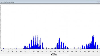
    At the end of the last temperature step, we sampled the cell with the Cirrus mass spec. There was no deuterium seen in the cell, none detectable anyway. The plentiful gas at 5k Pa did show a range of masses suggesting compounds of carbon, oxygen and nitrogen, with deuterium atoms attached. Perhaps someone familiar with catalytic chemistry at 100-250°C could find some sense in this. The important question is if the rapid pressure rise starting at 100°C was due to abnormal desorbtion of introduced D2, or from a leak that didn't appear during de-gassing the system at room temperature. The cell reached around 5E-5 Torr before heating, so any leak path must be highly temperature-sensitive.


    The experiment is ongoing, just approaching what we think is the critical temperature (250°C) for the possible onset of excess heat. So keep watching if you're in a convenient time zone. I will be posting a summary of findings tomorrow, and full analysis of the raw data files will follow when time permits.


    This is just the first of what I expect to be a series of tests, both with the currently installed mesh and with two fresh prepared sheets also on hand. If anything interesting is seen it will be reported here first, with complete documentation to follow.

    I have that same power supply for electrolytic work (plating etc.). Both the display data and the "regulation" are crude and prone to drift and jitter at low settings. The so-called regulation is merely adjustable current or voltage limiting, so that when a current limit is reached, the supply voltage is reduced to maintain that limit. If the actual current is below the set limit, the voltage is not automatically increased as would be done by a fully constant-current regulated supply. In operation it's a bit confusing, because whichever of the limit settings is reached first will be the one in control. This kind of operation is not unusual for inexpensive bench supplies, but it's definitely not "lab quality".

    Here's a link to my paper analyzing a LEC sample from Frank Gordon.

    https://magicsound.us/MFMP/LEC_Analysis-2.pdf


    My conclusions:


    * The sample cell produced ~220 nW / cm2 , and up to 1 volt into 100 megohms.
    * Surface morphology is complex and granular, particles ranging <100 nm - 2 um.
    * The co-deposition layer contains substantial amounts of Zinc and Sodium.
    * There is no significant x-ray emission from the sample cell 150 eV...100 keV .

    Are you still working on replicating the LEC?

    At this point, there are enough replications to demonstrate it is real. So I'm working on understanding it enough to design useful experiments. By useful I mean something that can improve the power yield and repeatability of the device.


    Alan Smith has shown that a wide variety of materials can be used, but not always with good repeatability. His draft report on that work is posted elsewhere on this forum. I've submitted a paper describing my LEC tests for presentation at Assisi if a time slot becomes available. I'll also post it here once I clean up a few details.

    Si-PIN detector, how close to the surface of the sample was possible to locate the detector?

    It was about 3 cm. I simply put the sample in my Hitachi 3030+ SEM, and ran the Bruker EDX system with the SEM electron beam off. The Bruker software doesn't seem to care, and its Quantax detector is extremely sensitive. The machine's vacuum system gets to around E-7 Torr, so the sample distance only affects the solid angle seen by the detector.

    The fogging of X ray film is caused by the unknown/uncharacterized radiation that causes that is also capable of causing gas ionization.


    I know you don’t believe that the radiation exists. But the fogging of X ray film and the ionization of gas is quite a big evidence for the existence of that radiatio

    Medical-grade X-ray film is typically designed for optimum sensitivity in the range of commercial x-ray sources. From available literature, that range is around 40-80 keV. There may be special films with lower peak sensitivity, and testing with UV photo film has been suggested. Dark room conditions are probably needed for that, as specified for the particular film used.


    Further, the mean free path of sub -1 keV x-rays in air is less than 1 cm [1]. So when I recently tested Frank Gordon's working electrode sample with a Si-PIN detector, I did it in vacuum, No emission was seen in the detection range of 150eV to 30 keV.


    [1] https://physics.nist.gov/PhysR…yMassCoef/ComTab/air.html

    In my opinion "bare" films have to be used to get something.

    I've given this some thought, but the difficulty of removing the film itself from the enclosure needs to be done in darkroom conditions. It should be possible with a red "safe light" and I'll give it a try, placing the film and the cathode in a black bag for the long exposure time needed.


    This is the film I use: http://dentalfilm.com/index.php/ar/prodotti/8-eco-30

    It's an Italian company, though the box I have says "Made In U.A.E".

    "ECO 30: compatibile con tutti gli apparecchi di radiografia 60 kV o 70 kV"

    But I do suspect that thermal events here are too fast for the camera to detect. I'm waiting to see if magicsound has any ideas about that.

    The camera I used is an Optris PI450, with 80 Hz frame rate. So it can capture thermal events on the order of 12 msec and 0.1 mm. I think both those are too large for any hot spots that might result from the LEC effect.


    Regarding use of x-ray film for detection, I ran three tests using self-developing dental x-ray films, laid directly on the active electrode for up to 12 hours. No artifacts or fogging was seen on those. But dental x-ray films are designed for sensitivity in the range 40-60 keV, and would thus not show lower energy emissions that might have been missed by the CdTe spectrometer.