I looked up the dimensions of a commercially available alumina tube closest to the 2 cm alumina tube used in the Rossi reactor. It was in millimeters 19.05OD x 14.30ID. The Lugano reactor was also covered with alumina heat fines and pure alumina cement which complicates things.
See
http://www.sifferkoll.se/siffe…10/LuganoReportSubmit.pdf
The temperature of the surface of the reactor refected the temperature of the heater wire more than the core of the reactor. The wire cast a shadow from the light produced by the core so the core was hotter than the heater wire.
Display More
OK so let's try to have a model with a hot core and wires. The thing I'm not sure about is this. The heater wires seem to be wound in a spiral configuration, but are they embedded in alumina? I would tend to think yes, but I'm not sure.
Also, once a model is running, it is easy to change the temperature of the course to test different hypotheses, including the 1450 C.
you drew the fuel core that touch reactor core, instinctively..
Therefore, the fuel is never drawn as touching the wall in Rossi's patent..
May be it is a central powder pellet...?
Good point, the label should be changed by replacing "fuel" with "reaction chamber" to avoid making unsupported assumptions.
Axil, how can you believe this? Look at the few centimeters of the heating wires that are sticking out from the dogbone end caps. They are producing an intense heat glowing like incandescent lamps. They produce the same heat per length unit inside the dogbone but there they are in a more compact spiral configuration. But you believe that they appear as shadows. Just because the stupid Lugano report said so or what?
That's interesting but you are forgetting the thickness of the alumina. Let L_w be the radiance of the glowing wires. This depends on their emissivity and temperature.
Inside the reactor, you have (to appease skeptics, allegedly) a source of heat that glows with a radiance L_r, some thickness x1 of alumina, then glowing wires of thickness x2, then some thickness x3 of alumina.
Ignoring scattering within the alumina, at the surface of the reactor, regions where the reactor glow is not shadowed by the heater wires have radiance
L1 = L_r (1-R)^2 exp(-C (x1 + x2 + x3))
where R is the reflectivity and C [cm^-1] is the effective scattering coefficient of alumina,
and x1 + x2 + x3 is the thickness of alumina, from the glowing reactor core to the surface.
In the shadowed region, we assume that we only see the hot wires thru a thickness x3 of alumina so that the radiance is
L2 = u L_w (1-R)^2 exp(-C x3)
where u is a parameter that varies from 1 to 3 to describe the extent to which the three heaters contribute to the unshadowed radiance; if there was no scattering, because the wires do not overlap, we would have c equal to one. But we can adjust c to partially account for scattering, although c cannot exceed three because there are only three wires. I think u would be closer to 1 than 3.
Let S = L2 / L1 (< 1) be the shadowing ratio.
By looking at the red channel of the image from fig. 12a in the Lugano report, I have measured that the wire shadows cause a dip from 1.00 to 0.75 in the signal; the background level measured from alumina nearby at approximately the same illumination angles is about 0.72, so that the signal goes from 0.25 to 0.03, implying S ~ 0.12.
We have
S = L2 / L1 = u L_w (1-R)^2 exp (-C x3) / L_r (1-R)^2 exp(-C (x1 + x2 + x3))
= u L_w / L_r (exp (-C (x3 + (+x1 +x2 +x3)))))
= u exp(C(x1 + x2)) L_w / L_r
Therefore
ln (S L_r / (u L_w)) = C(x1 + x2)
And thus the first constraint is S L_r / u L_w >= 1.
Hence L_r/L_w >= u / S
For u=1 we need L_r/L_w > 8.4 but if we take u=3 we need L_r/L_w >= 25.
(This is the ratio of integrated, excess radiances in the red channel.)
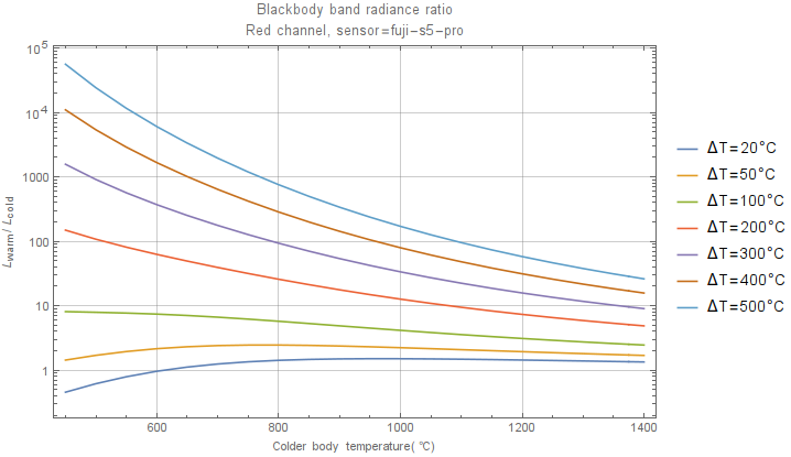
If we assume that the wire and the core have the same emissivity, a 75 degree difference if the wire is at 450 degrees, to a 150 degree difference if the wire is at 1000 degrees is necessary to give an 8.3:1 ratio, while these numbers go up to 150 degrees at 450 to 300 degrees difference at 1000 degrees for a ratio of 25.
According to the latest plots aboveplot below, a 50 degree difference is sufficient to cause a factor of 4× change in the radiance in any of the visible bands.
For the second constraint, we have x1 + x2 = ln (S L_r / (u L_w))/C
Based on Yamashita 2008, around 600 nm we have C ~ 2.0.
A minimum possible value for x1 + x2 would be x12_min = 2 mm.
Thus
ln (S L_r / (u L_w)) / C > x12_min
which is
u > exp(C x12_min) / (S L_r/L_w)
For u=1 we get 1.5 / (0.12 * 8) = 1.56 so it is true, and for u=3 we have 1.5 / (0.12 * 25) = 0.5 and it is true by default
In fact we can solve for L_r/L_w and what we really need is exp(C x12_min)/S = L_r/L_w ~ 12.5
Therefore wire shadows having a contrast of 8:1 as seen in the Lugano fig 12.a images are possible provided the temperature differential between the heater wires and the core is on the order of 100-200 C.
EDIT: Black body band radiance ratio plot.