stranger
Member
- Member since May 12th 2018
- Last Activity:
Posts by stranger
-
-
The Time machine
(translated by Google)
In the vicinity of a great mass as planets or stars or black holes, the ("space_time") it is very curved, that is concentrated, and an external observer sees that in the vicinity of those mass the time flows more slowly.
The purpose of this time machine is to do the exact opposite, that is, to straighten the ("space_time"), that is, to dilate it.
Suppose you need at least 4 days to do a thesis, but you forgot to do it and you have to give it in 5 minutes.
How do solve the problem ?
You can say that you have forgotten or you need this kind of time machine.
With a time machine you can do the 4-day job in just 5 minutes; 4 days have passed for you, but only 5 minutes have elapsed for the others.
You would earn a very interesting amount of time.
This could also be useful for owners of factories who want to make the most of their slave workers.
How is the design of this time machine ?
These are simply 2 rotation axes placed perpendicular to each other (a carpenter would say "in team")
The 2 imaginary axes must intersect perfectly otherwise we get dynamic imbalances that are not going well.
If 2 axes of rotation are required, then 2 electric motors are required.
To distinguish them in the drawing one engine is green and the other is pink.
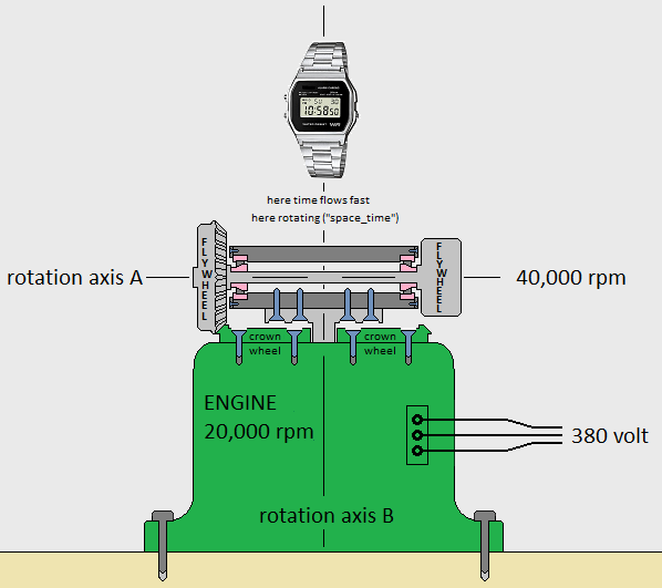
The purpose of the pink engine is to generate a very strong gyroscopic effect, so strong as to be almost inflexible.
The purpose of the green engine is to quickly rotate the rotation axis produced by the pink engine.
The effort wich the green engine must has to do is remarkable because the gyroscopic effect generated by the pink engine is remarkable.
The pink engine has to do 40,000 rpm, instead the green motor has to do 20,000 rmp .
We must remember that the gyroscopic effect has the tendency to keep the axis of rotation fixed in space.
The torque generated by the green engine should generate heat or potential energy, instead it does not generate any of the two forms of energy, so it seems that the famous law of energy conservation is not respected.
In fact: in order for the law of conservation of energy to be respected, it must necessarily happen that the ("space_time") that is above the pink motor must start to turn on itself and then accelerate with a rotary motion.
Even if the whole laboratory does not rotate on itself, it is as if it were turning on itself and any non-constrained objects that are close to the machine would be pushed outwards, even an external observer feels a force that drives him away from the time machine.
The rotation of ("space_time") generates the expansion of ("space_time"), right where there is the imaginary center of the rotation axis B.
The exact opposite of what happens happens near a large mass like a planet or star or black hole.
Note: you should not exaggerate to speed up too much the passage of time, in other words you should not exaggerate to dilate too much ("space_time"); because the excessive expansion of ("space_time") could cause a tearing of ("space_time"), the tearing of ("space_time") could cause a gigantic explosion.
---------------------------------------------
---------------------------------------------
It is possible to make the time machine even with an ONLY motor, but in this case the 2 flywheels cannot be of the same geometry.
One flywheel must have a crown gear, so a bevel gear pair is required.
In this case of a single motor, the brushes are not necessary but the friction of the gears is considerable, would it be more appropriate ?
those 2 light yellow pieces are the thrust bearings, whereas the pink ones are 2 normal standard ball bearings.
Obviously everything must be dynamically balanced, so the mass of the flywheels must be precise in order to do everything in the center and balanced.
-
(this has been translated with google)
These are simply 2 rotation axes placed perpendicular to each other (a carpenter would say "in team")
The 2 imaginary axes must intersect perfectly otherwise we get dynamic imbalances that are not going well.
If 2 axes of rotation are required, then 2 electric motors are required.
To distinguish them in the drawing one engine is green and the other is pink.
The purpose of the pink engine is to generate a very strong gyroscopic effect, so strong as to be almost inflexible.
The purpose of the green engine is to quickly rotate the rotation axis produced by the pink engine.
The effort to make the green engine is remarkable because the gyroscopic effect generated by the pink engine is remarkable.
The pink engine has to do 40,000 rpm, instead the green motor has to do 20,000 rpm.
We must remember that the gyroscopic effect has the tendency to keep the axis of rotation fixed in space.
The torque generated by the green engine should generate heat or potential energy, instead it does not generate any of the two forms of energy, so it seems that the famous law of energy conservation is not respected.
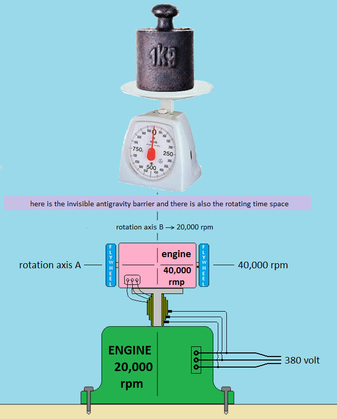
In fact: in order for the law of conservation to be respected, it must necessarily happen that the ("space_time") that is above the pink motor must start to turn on itself and then accelerate with a rotary motion.
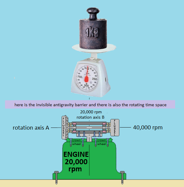
This creates an barrier anti-gravity that prevents gravity from passing, so one kilogram placed on a scale weighs will be less than 9.8 newtons.
The more we increase the speed of the rotation axis A, the more the antigravity barrier becomes efficient
Note: you should not exaggerate to shield the gravity too much because the excessive shielding of the gravity could provoke a tearing of the ("space_time"), the laceration of the ("space_time") could provoke a gigantic explosion.
------------------------------------------------------
------------------------------------------------------
it is possible to make the anti-gravity barrier even with an ONLY motor, but in this case the 2 flywheels cannot be of the same geometry.
One must have a crown gear, so a bevel gear pair is required.
In this case of a single motor, the brushes are not necessary but the friction of the gears is considerable, would it be more appropriate ?
those 2 light yellow pieces are the thrust bearings, whereas the pink ones are 2 normal standard ball bearings.
Obviously everything must be dynamically balanced, so the mass of the flywheels must be precise in order to do everything in the center and balanced. -
it is possible to make the big bang machine even with an ONLY motor, but in this case the 2 flywheels cannot be of the same geometry.
One flywheel must have a crown gear, so a bevel gear pair is required.
In this case of a single motor, the brushes are not necessary but there is the friction of the gears. -
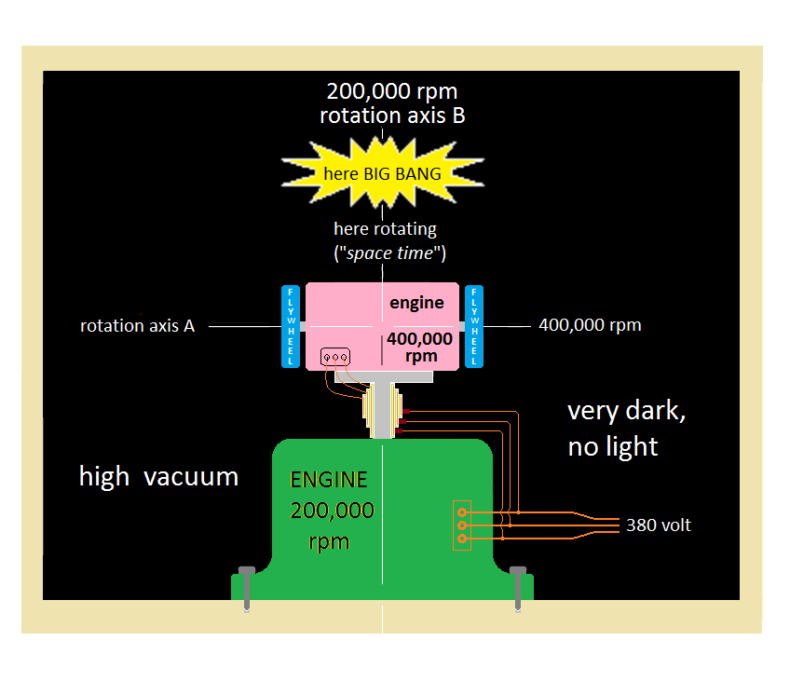
(it is traslated by google chrome)
These are simply 2 rotation axes placed perpendicular to each other (a carpenter would say "in team")
If 2 axes of rotation are required, then 2 electric motors are required.
To distinguish them in the drawing one engine is green and the other is pink.
The purpose of the pink engine is to generate a very strong gyroscopic effect, so strong as to be almost inflexible.
The purpose of the green engine is to quickly rotate the rotation axis produced by the pink engine.
The effort to make the green engine is gigantic because the gyroscopic effect generated by the pink engine is gigantic.
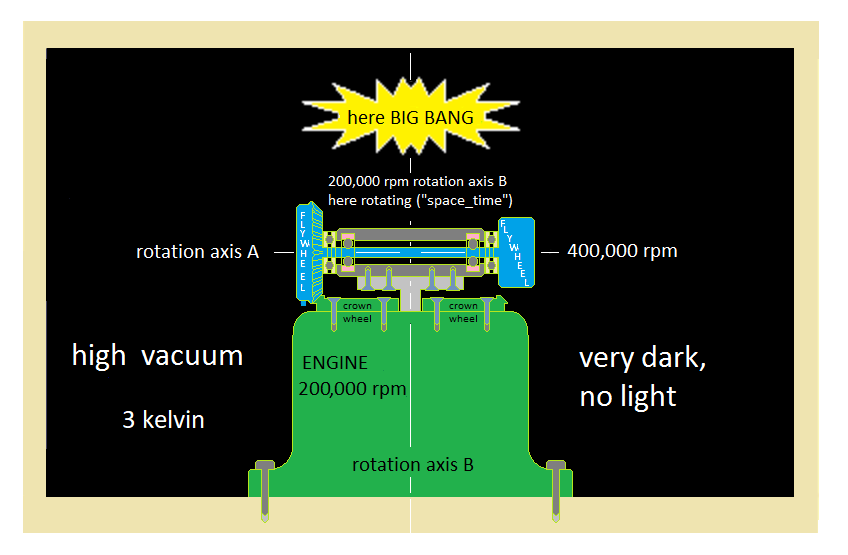
The pink engine must perform 400,000 rpm, instead the green motor must perform 200,000 rpm.
Both engines must be inside a room where there is high vacuum, and also there must be a temperature of a few degrees kelvin: 1 or 2 or 3.
The fans of the engines can not cool the engines because as already explained above, in fact inside the room is not air because there is an extreme vacuum.
Although the fans can not cool the engines, the windings do not heat up because a few degrees kelvin triggers the strange phenomenon called "superconductivity".
Superconductivity allows you to create very strong magnetic fields and the green motor provides a huge torque, able to overcome the gigantic gyroscopic effect.
I remember that the gyroscopic effect has the tendency to keep the axis of rotation fixed in space.
The gigantic pair generated by the green engine should generate heat or potential energy, but it does not generate any of the 2 forms of energy, so it seems that the famous law of energy conservation is not respected.
In fact: in order for the law of conservation to be respected, it must necessarily happen that the ("space_time") that is above the pink motor must start to turn on itself and then accelerate with a rotary motion.
Even if the room does not turn on itself it is as if it were turning on itself and any non-bound objects that are inside the room would be pushed outwards against the walls of the room.
Incredible! An outside observer sees that the room is still but sees that the objects are pushed outwards and even the observer himself feels a force that moves him away from the room itself.
The rotation of ("space_time") generates the expansion of ("space_time"), right where there is the imaginary center of the rotation axis B.
Subsequently the same conditions are created that existed before the famous BIG BANG, which already occurred about 13.7 billion years ago.
Before the BIG BANG there was no ("space_time").
When it occurs that the ("space_time") does not exist, an external observer could see that time flows at infinite speed and therefore everything becomes probable ... Also the BIG BANG.
The extreme dilatation of the ("space_time") that occurs above the pink engine causes a tearing of the ("space_time") and bursts the BIG BANG.
The destructive power of the artificial BIG BANG is exactly the same as that which occurred 13.7 billion years ago, impossible to write the number of megatons, it would take many numbers with many exponents on top of each other. -
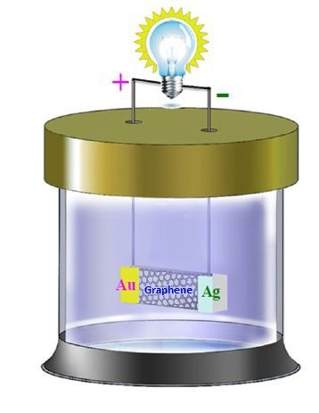
Researchers at Hong Kong Polytechnic University claim to have invented a new kind of graphene-based "battery" that runs solely on ambient heat. The device is said to capture the thermal energy of ions in a solution and convert it into electricity.
The results are in the process of being peer reviewed, but if confirmed, such a device might find use in a range of applications, including powering artificial organs from body heat, generating renewable energy and powering electronics.
Ions in aqueous solution move at speeds of hundreds of metres per second at room temperature and pressure. The thermal energy of these ions can thus reach several kilojoules per kilogram per degree.However, until now, little work had been done on finding out how to tap into this energy and produce power from it.
Zihan Xu and colleagues made their battery by attaching silver and gold electrodes to a strip of graphene – which is a film of carbon just one atom thick. In their experiments, the researchers showed that six of these devices in series placed in a solution of copper-chloride ions could produce a voltage of more than 2 Volt.
This is enough to drive a commercial red light-emitting diode.
The technology is quite different to conventional lithium-ion batteries, for example, which convert chemical energy into electricity. “The output of our device is also continuous and it works solely by harvesting the thermal energy of the surrounding copper-chloride ions, which, in theory, is limitless,” says Xu.
According to the researchers, the battery works rather like a solar cell. The copper ions (Cu2+) continually collide with the graphene strip in the battery. This collision is energetic enough to displace an electron from the graphene. This electron can then either combine with the copper ion or travel through the graphene strip and into the circuit.
Since electrons move through graphene at extremely high speeds (thanks to the fact that they behave like relativistic particles with no rest mass), they travel much faster in the carbon-based material than in the ionic solution. The released electron therefore naturally prefers to travel through the graphene circuit rather than through the solution.
This is how the voltage is produced by the device, explains Xu.
---------------------------------------------------------------------------------------
Boosting voltage output
The researchers also found that the voltage produced by the device could be increased by heating the ionic solution and accelerating the Cu2+ ions with ultrasound. Both of these methods work because they increase the kinetic energy of the ions. The voltage also increases if the copper-chloride solution is more concentrated with Cu2+ ions, because the density of Cu2+ on the graphene is then greater. Other cationic solutions can be employed too, such as Na+, K+, Co2+and Ni2+, although these produce lower voltage outputs.
The unique atomic-layer nature of graphene is crucial for this battery, say the researchers, who also experimented with graphite and carbon-nanotube thin films. They discovered that these materials only produced low voltages of around microvolts, which could be regarded as noise.
Bor Jang of Nanotek Instruments in Dayton, Ohio, who has worked on making supercapacitors from graphene, says that the concept described looks "very interesting" but that "more work will be needed to assess whether the approach could provide sufficient energy or power density for practical uses".
For its part, the Hong Kong team now plans to improve the power output of its graphene-based device and further investigate how it works. -
--- begin calculation ---
Pa7 = power absorbed by the motor 7 at steady speed that is after starting the engine 7
Pa8 = power absorbed by the motor 8 at steady speed that is after starting the engine 8
Pa9 = power absorbed by the engine 9 at steady speed that is after starting the engine 9
Pe5 = power delivered by the alternator 5 when fully operational that is after starting the alternator 5
Pe6 = power supplied by the alternator 6 when fully operational that is after starting the alternator 6
Pe5 = Pe6
Petot = Pe5 + Pe6
Petot = 2 * Pe5
Petot = 2 * Pe6
friction7 = loss of power due to the friction of the bearings inside the engine 7
friction8 = loss of power due to friction of the bearings inside the engine 8
friction9 = loss of power due to friction of the bearings inside the engine 9
friction7 = friction8
Pa7 = friction7
Pa8 = friction8
Pa9 = friction9
Pe5 > [(Pa9 + Pa7) * 10]
Pe6 > [(Pa9 + Pa8) * 10]
Petot > {2 * [(Pa9 + Pa7) * 10]}
Petot > {2 * [(Pa9 + Pa8) * 10]}
--- end calculation ---
-
-
In my opinion the best alternative to the lern is a small cyclotron because the cyclotron transmutes the elements.
For example, if a small cyclotron is loaded with rarefied helium gas and the target is a piece of beryllium, by starting the cyclotron, the beryllium piece emits an intense neutron flux that can transmute all the elements you want.
-
I know that the cyclotron transmits the elements.
For example, if a small cyclotron is loaded with rarefied helium gas and the target is a piece of beryllium, by starting the cyclotron, the beryllium piece emits an intense neutron flux that can transmute all the elements you want.
-
Beryllium making is not the same thing as using beryllium.
The housewife uses steel pots but she does not have to forge them by breathing incandescent steel vapors.
The wooden wardrobe is fine, but it is not good to cut the wardrobe and breathe the wood dust.
-
It is sufficient to have a very small cyclotron that weighs 12 tons, to accelerate helium nuclei that automatically collide against a beryllium target.
The piece of beryllium emits neutrons that can be used to make nuclear transmutations and therefore also to make LENR in an efficient and exciting way.
Therefore the cyclotron must be loaded with rarefied helium gas.
The neutron flux intensity is proportional to the density of helium gas.
Warning ! Have not to want too dense a flow of neutrons because then you would need a electric central to feed that small cyclotron.
------------------------------
The televisions make believe that beryllium is a very dangerous material and if you touch it you die instantly struck, in reality with the beryllium you could also make the cans of the cocacola
-
We have to imagine 2 axes of rotation: the axis of rotation of the wheel that we identify with the code 55, and the axis of rotation of the handlebar that we identify with the code 57.
Having ascertained that the rotation axis 55 does not rotate, that is, it performs zero revolutions per second, we make a steering of the handlebars to the left or right, so for a moment the rotation axis 57 rotates. Steering with the wheel stopped that is accelerating the axis of rotation 57, we realize that our muscles have to do some mechanical work.
That mechanical work is caused by ...
- Acceleration of the wheel mass (the rotation axis 55 is always stopped).
- Acceleration of the handlebar mass.
- Air friction.
- Tire friction on the asphalt.
We realize that muscular effort is not small because the friction of the rubber on the asphalt is big.
We want to remove the friction of the rubber on the asphalt, to do so we have to lift the front wheel of the bicycle and then fix an iron beam that keeps it lifted permanently.
We repeat the work to steering left or right, and we realize that muscle strain is less because the friction of the rubber on the asphalt has been removed.
Now that mechanical work is caused by ...
- Acceleration of the wheel mass (the rotation axis 55 is always stopped).
- Acceleration of the handlebar mass
- Air friction.
Now we mount a wheel on a drill and place the wheel on the front wheel of the bicycle, therefore the front wheel of the bicycle begins to accelerate until it reaches a high speed, for example 2000 rpm.
We repeat the work to steering left or right, and we realize that muscle strain is greater than before when the front wheel was stopped.
Now that mechanical work is caused by ….
- Acceleration of the wheel mass in accordance with the rotation axis 57.
- Acceleration of the handlebar mass.
- Air friction.
- gyroscopic effect
Lifting the wheel and turning it, we replaced the friction of the rubber with the gyroscopic effect.
In theory, if the wheel does one million rpm, it would be impossible to steer, not even the strongest man in the world could steering.
It is possible to consider that bicycle front wheel as if it is a flywheel.
There are no doubts: the angle of an axis of rotation of a flywheel tends to remain fixed in space.
We want to design a mechanism that exploits this trend.
How you do it ?
It is not easy to design it because if an object has a tendency to move, it is easy to exploit its energy because I connect that object to the pivot of an electric generator and produce electricity, but in the case of the gyroscopic effect the situation is inverse because the object wants to stay still.
It is paradoxical! ... We are very demanding and we want to get kinetic energy from something standing still.
Although the object wants to be still, we have to show that it wants to move, so the world has to turn around it or at least a small part of it..
I connect the handlebars of that bike to a
dynamo, and then I make sure that the floor turns on itself; but we must not be
stupid to turn the whole floor for real, it is enough to turn only the stator
of the dynamo.But even in this way we have not get anything because the energy produced by the dynamo is equal to that which we have to spend to power the engine, indeed the energy produced is lower because there are the inevitable losses caused by various friction.
In other words, the mechanical twist to turn the stator of the dynamo fully discharges on the electric motor.
It's still not good: we have to design a mechanism in which the mechanical torsion of the stator of the dynamo must not be discharged on the engine.
The idea is to multiply so many things for two: 2 dynamo, 2 bicycle wheels, 2 dumbbells.
But the engine is only 1 so the engine is an exception to the rule.
By doing so, the mechanical twists of the dynamo stators are not in opposition to the motor, in other words the motor turn effortlessly as also the motors which have a rotation axis of 55 and 56 turn effortlessly.
An engine that turn effortlessly anyway absorbs some energy because there are the inevitable frictions.
It is during the start-up of the engines that there is great absorption of energy, at that moment there are not only the frictions, there are also large masses to be accelerated up to the speed of the regime.
There remains the technical problem of how to bring energy to the engines and take energy from the dynamo, not easy to solve this problem because everything is rotating, everything is spinning, and would need a "super collector" that we could also call "super distributor".
If we consider that it is important to understand the physical principle then the technical problems of super collector are of secondary importance and an engineer will have to solve the technical problem of secondary importance.
Here is an example of a super collector or distributor, but the dynamos have been replaced by alternators so the wires that come out are 3 and not 2.
(translated by google)
IDENTIFICATION CODES
1,2,3,4) flywheel
5 and 6) three-phase alternator
7,8,9) electric motor continuous voltage
10) thrust bearing
11) collector and support base for alternators
12,13,14,15,16,17,18,19,20,21,22,23) graphite brush
24) cover
25) ball bearing
26.27,28,29) bolt
30,31,32,33,34,35,36,37,38,39,40,41,42) tube of plastic that is electrical insulating
43,44,45,46,47,48,49,50,51,52,53,54) tube of copper that is electric conductor
55,56,57,58,59) imaginary axis of rotation
60,61) voltage elevator transformer
62,63) high voltage pylon
64) voltage reducer transformer
65) Graetz bridge rectifier
66) manual switch
67) starting accumulator
68,69) washer
70) resistor
71) relay contact delayed to 5 seconds excitation
------------------------------------------
By closing the switch 66, continuous electric voltage arrives at the graphite brush 19 and also to the motor 9, so the motor 9 starts to accelerate the base 11.
From the graphite brush 19 electrical voltage arrives to the copper tube 50 which connects the electrical voltage to the graphite brushes 20 and 22.
All brushes have a small spring whose purpose is to hold the brush against a copper tube, but for simplicity in the design the small springs have not been drawn.
When electric voltage is reached at the brush 20, the electric motor 7 starts to turn and then the flywheels 1 and 2 turn.
When electric voltage arrives at the brush 22, it happens that the motor 8 starts to turn and then the flywheels 3 and 4 turn.
All four flywheels 1 2 3 4 are of heavy solid steel.
Because of the gyroscopic effect, the imaginary rotary axes 55 and 56 have the tendency to maintain the same angle in the space around them, it follows that if the base 11 is rotating, the rotors of the alternators 5 and 6 are forced to turn. producing electricity which is sent to six copper tubes which are 43,44,45,46,47,48.
The three copper tubes 43,44,45 feed the voltage transformer 60, instead the three copper tubes 46,47,48 feed the voltage transformer 61.
The secondary circuit of the elevator transformers is connected to the high voltage cables, this is normal as in all power stations.
It is already known that any electric motor in continuous needs at least 2 wires, in one wire the electric current and the other is considered by convention the return of the current, the copper tube 49 collects the return electric current and then complete the electrical circuit.
Since the mass of the base 11 is noticeable with respect to the rated power of the microscopic motor 9, it is necessary to complicate the electric circuit so as to ensure that the starting electric current is limited; to do this there is the electric resistance limiter 70 and the delayed relay 71 normally open.
By closing the circuit by means of the switch 66, the delayed relay does not close immediately so the electric current is forced to pass through the electric resistance limiter, but after about 5 seconds, the delayed relay 71 short-circuits the electrical resistance 70 and then arrives on the motor 9 full tension.
By mistake there could be an obstacle that blocks the base 11 and therefore the motor 9 so unfortunately the relay gives the consent even when it should not, in this case an automatic thermal protection switch must intervene to avoid burning the motor winding 9.
Instead of the delayed relay, a revolution counter could be placed; the tachometer is safer but it also costs more, or instead of the delayed relay you could put a watt regulator that excludes the resistance only if the number of revolutions exceeds a certain predetermined value.
There are numerous methods to soften the start of an electric motor, but there is no willingness to explain them all.
The imaginary rotational axes 57 and 58 rotate in the opposite direction to the rotation axis 59, it has not importance which direction the motor 9 rotates, but if by looking at the top we decide that the motor 9 must rotate clockwise, the rotors of the two alternators will turn counterclockwise.
As a consequence both the alternator stators will suffer an anti-clockwise mechanical twist which will be released on the base 11.
It will be unloaded on the base 11 because the alternator stators are bolted onto the base 11 by means of the bolts 72,73,74,75.
It is very important to take into account the mechanical twists acting on the base 11 and the direction of rotation of those twists.
The resulting vector of both counterclockwise twists will result in a total central mechanical twist whose rotation center is precisely the rotation axis of the motor 9, so the motor 9 is privileged by those twists and there is no contrast as is normal to think .
The motor 9 is pushed by 67 and is also driven by the mechanical twists generated by the stators of the two alternators.
The two mechanical twists are in one sense and by reaction the whole base is accelerated in the opposite direction, this is the basis of the principle of classical physics according to which every action corresponds to an equal and opposite reaction.
The law of action and reaction favors the engine 9.
This means that after the start-up period, the engine 9 could also function as an electric generator.
The flywheels 1,2,3,4 must perform many rpm per minute, minimum 2800 rpm if it is possible to do 28 thousand rpm is better, without exaggerating too much otherwise the steel of the flywheels will deform due to centrifugal force.
instead the engine 9 can turn slowly, 60 rpm per minute are sufficient but even 30 rpm are sufficient
The flywheels 1,2,3,4 are the most important components, all the other components are of secondary importance, if those 4 flywheels are still, even all the other things stop.
The 1,2,7 components represent the first gyroscope, and the 3,4,8 components represent the second gyroscope.