Brian Albiston Verified User
  • Member since Feb 9th 2015

Posts by Brian Albiston

    @me356
    Are you willing to share your Nickel prep procedure?


    My procedure for my last run was:
    Heat for 1 hour in air at 250C
    Heat 1 hour at 115C under vacuum
    Reduce, 20 PSIG Hydrogen at 115C overnight
    Heat 1 hour at 150C under vacuum
    Reduce, 20 PSIG Hydrogen at 150C 10 hours
    Heat 1 hour at 150C under vacuum
    Reduce, 20 PSIG Hydrogen at 300C 3 hours
    Store under Hydrogen


    Thank you for any suggestions you have.

    @me356
    Thank you so much for taking the time to answer our questions. You have already brought so much clarity to what I have seen and witnessed with my experiments.


    Just a couple of quick questions:
    -Are you using bulk Lithium or powdered Lithium for these experiments?
    -In the video you posted what was the temperature at when you initiated excess heat?
    -Did you initiate excess heat by a sudden reduction in pressure to initiate Lithium boiling?


    @Hank Mills
    Look up the Antoine equation for Lithium. http://webbook.nist.gov/cgi/cbook.cgi?ID=C7439932&Mask=4&Type=ANTOINE&Plot=on

    @me356
    As a "replicator" (Does this term have any meaning any more? We are investigators and researchers.) that has never stopped and has also spent thousands of dollars and hundreds of hours on LENR investigation, I would appreciate any pointers you can give me.


    I have a Hydrogen source and vacuum pump that I currently use to remove Oxides and load Hydrogen in the Nickel prior to testing.

    Post run calibration completed and can be seen here compared with the fueled run: https://plot.ly/825/~fear_nuts/


    Every effort was made to make the post calibration as close to the active run as possible, including Hydrogen in the cell to account for it's high thermal conductivity.


    It is not much, but there is a definite shift in the data in the fueled run. I estimate that there is about a 3-4 deg C shift in the fueled run corresponding to a COP of ~1.1. A lot was learned on this test so hopefully we can improve on that COP from here.


    All of the test data and lots of pictures can be found here: https://www.dropbox.com/personal/albiston fusion/test data/Reactor 6 - Conduction 1/Test1

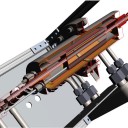
    The test used a stainless steel fuel tube which contained 3g AH50 Ni, 0.45g LiAlH4, and 0.3g Nanoshel Li. The Ni was heated in air and Hydrogen reduced using the procedures in the MFMP "signal". The SS fuel container was contained in an 18" Alumina tube with a thermocouple butted up against the SS fuel container to measure the core temperature. The 18" alumina tube was wound with Kanthal A1 heating coils and placed inside two concentric Alumina tubes with a gap filled with lead (see the dropbox pictures). The lead jacket was then heated to lead melting and additional lead was added to completely fill the gap between tubes. A thermocouple was placed inside the lead jacket and a second thermocouple was placed on the exterior of the outer Alumina tube. These two thermocouples acted as a conduction calorimeter. A conduction calorimeter works by first having a good conductor (molten lead) accumulate and spread out the heat and then measuring the temperature differential across a second less good conductor (Alumina tube). Ideally the temperature difference will be linear versus heat generated inside. Mine turned out to be close to linear but not quite likely due to radiation from the outer layer.


    Calibration:
    https://plot.ly/803/~fear_nuts/
    https://plot.ly/813/~fear_nuts/
    Calibration only proceeded to 1000C and 540W because my power supply ran out of juice. I will run additional calibrations covering full range for future tests.


    The test was started Saturday night with additional reducing/vacuum cycles. Test continued until this morning when I had to end it because of test controller problems. I'm not sure what the failure was yet, but it seems like either the core thermocouple or the thermocouple embedded in the molten lead jacket failed.


    I think this chart shows the results the best:
    https://dashboards.ly/ua-ocR57qTE73RUFWTYA2FkUB
    The calorimeter temperature differential appears to be significantly higher on the active run, but uncertainties are large. Comparing active and calibration curve fit temperature differentials versus power input the COP can be estimated to be up to 1.2. Further testing will need to be completed to reduce uncertainties, but I consider this promising that the MFMP "signal" procedures will result in more consistent positive results.

    @s_grey, Thank you for sharing your experiments. I recommend on your next experiment to use 2 thermocouples, preferably with one located in a slightly cooler area of the reactor. In my experiments I have seen several cases where type K thermocouples degrade above 1200C and will give false high readings. This can give the illusion of excess power being generated when it is not. By having two thermocouples you can compare them to ensure they are in agreement and if one is located in a cooler section it will be less likely to degrade and give false high readings. Hopefully you can eventually move into some type of calorimetery.


    When the effect seemed to appear and the power was reduced did the glow appear constant?


    Best of luck on your experiments.

    I want to give a report on another one of my failed tests and hare brain ideas so that nobody else bothers repeating it. I came up with the brilliant (but apparently very flawed), theory that Rossi’s original catalyst was radioactive. I had noticed that my (questionably) most successful test had been conducted over a slab of slightly radioactive granite. All of my subsequent failed tests have been shielded from this granite.
    Several replicators have also observed that Russian researchers in Moscow seem to have had more success than others with the same system. I read somewhere that many areas of Moscow have elevated radiation levels due to old cold war radioactive material dumps.
    I theorized that Rossi’s original reactors included lead shielding not to shield the reaction (since we now know that very little ionizing radiation is produced by the reaction), but to hide the identity of the true catalyst hidden inside. I presumed that his later reactors had moved on to another non-radioactive catalyst (possibly pure Ni 62) and hence no more need for lead shielding.
    I completed a test two weeks ago heating 3g Hunter AH50 Ni, 0.3 g LiAlH4, and 0.5 g crushed “Radioactive Red” Fiestaware. Fiestaware was dinnerware from the 30’s that the glaze was made from Uranium Oxide. A small shard of the dinnerware can have as high as 30,000 CPM. The mix was heated over 12+ hours using the standard protocol up to 1150-1200C and allowed to soak at 1150C overnight. No evidence of excess heat.

    https://www.dropbox.com/s/1mc4ppeq5tv7dtw/Fiestaware Test.png?dl=0

    COP is slightly above 1 in both calibration and active runs because my input power meter measures a bit low.

    @jeff
    Very, very nice setup. I would like to learn more about your calorimetry method as I have found water calorimetry is a big pain for many reasons.


    I have a question for you about the Lithium you are using. Is this bulk Lithium or Lithium powder? I have found it very difficult to get bulk Lithium to mix with the Nickel powder because of its high surface tension. The Lithium tends to hug the walls of the reactor (where it will destroy the reactor if it is alumina) and the Nickel powder migrates to the center of the reactor. If you are using bulk Lithium then I would be surprised if it is coating the Ni powder which I assume is desired. This is one reason why LiAlH4 is a convenient Lithium delivery method.

    Axil, I wish my silence was because I had been successful. Unfortunately it is just because I haven't had time to be on-line the last couple of weeks. I just completed a very long thermal cycling test that I will post results on soon. No excess heat unfortunately. I hope next to complete a test with added graphite. I will try and do a better job of keeping everyone updated.

    @Optist Yes we have tried it. Several interesting things I've noticed:
    1. It absorbs all of the Hydrogen creating a strong vacuum at around 500C (I'm remembering these temps off the top of my head, I may be off quite a bit).
    2. This Hydrogen is absorbed when creating LiH.
    3. The molten Li is extremely hard on Alumina reactor vessels creating cracks.
    4. When the temperature is raised above ~650C the LiH starts to decompose releasing Hydrogen.
    5. The increase in Hydrogen pressure now breaks your weakened reactor vessel and your test is over.
    6. Bulk Li has extremely strong surface tension forces causing it to crawl up the wall of the reactor.
    7. The Ni fuel all migrates to the center of the reactor and does not mix with the Li.


    Actually Tom clay tour of Los Alamos National Labs did his own first principles test of the hypothesis. Was able to reliably generate tritium 12 out of 12 times using this method. His pulses were too wide to generate helium as a primary end product.


    @BEC, I'm going to make a leap of logic from your small number of high quality postings here and not-so-subtle choice of handle that you are associated with Briollouin Energy Corporation. I would like to know what you think of the Parkhomov/Rossi replication efforts ongoing by many of us amateurs and if you would like to see more Brilouin style replication efforts? Would you be willing to assist MFMP in a Briollouin style replication? Are you waiting for patents to be granted before you encourage more open replications?


    I apologize if my leap of logic was incorrect.

    @wizkid, can you describe your reactor construction?

    • It looks like you are using alumina or mullite tubes and sealing the ends with some sort of cement. What cement are you using? Do you have any idea if you are able to maintain a hermetic seal?
    • Are you individually wrapping each tube with Kanthal or nichrome wire or do you place each tube in a larger tube wrapped with heating wire?
    • It looks like you are then placing the reactor and heater assembly in refractory insulation. Using this method what temperatures are you able to attain? What is the longevity of your heaters?
    • What size tubes are you using?
    • Can you describe your fuel? Amount and types of constituents?
    • What is your drive current? AC/DC or something in the middle?
    • Do you use a PID controller or manual control?
    • Are you just measuring the temperature of the insulated chamber? Do you have a thermocouple on the reactor tubes?
    • It looks like you have two tubes in each insulated chamber? Are they both fueled or is one a control?
    • How are you going to look for excess heat? Simple temperature vs input power comparison with a calibration run?

    I understand if you would prefer not to answer any of these questions until you are ready to release a report. Thank You!

    Thanks for very interesting comments.


    Here is my fuel container in the attachment before fuel loading.
    Both screw-threads were sealed and mounted so it can hold firmly.


    In two weeks new SiC elements should arrive to me so I will be improving the design.
    The biggest issue for me is to make container for the fuel container that will keep Hydrogen gas inside and all will fit in the SiC element / heater.


    me356, Thank you for the picture of your fuel container. Is it just a threaded tube with standard stainless cap screws plugging the ends? Very simple design, I hope it works. What do you plan to use to seal the threads and keep it hydrogen tight?