can Verified User
  • Member since Jan 20th 2017

Posts by can

    Wyttenbach

    I'm assuming that charges are going to flow along the axis shown in this more abstract representation of the experiment and that the resulting current (what you're calling electrolyte current?) will produce concentric magnetic field lines along it. I'm not entirely sure what you're asking me to do:


    Of course it's entirely possible that I have some fundamental misunderstanding of the processes involved.

    Wyttenbach

    The electrodes+magnet arrangement was as follows; it most probably wasn't clear from the overexposed photos:


    I can't guarantee that the magnetic field was perfectly parallel to the applied current, however. For instance, the magnet isn't symmetrically shaped.


    In other news, the periodic signal in Geiger counter measurements is still there, perhaps even slightly more present than it was earlier, although more days will need to pass to be sure.


    Longview

    I think the context of this reference is of stable solid hydrides under standard conditions. Basically I wanted to point out without linking the usual paper often cited on the subject that very little hydrogen can normally get absorbed in the lattice of Nickel metal. So is the pressure decrease actually absorption? Or adsorption on the surface of segregated pores? Or something else instead (e.g. RM/UDH formation as speculated in the discussion above) ? I don't feel that one should accept without further questions or investigation that a large pressure reduction upon hydrogen admission is simply the result of H absorption into the Ni lattice.

    For the very few who care (copy/pasted from my notes, which I try to keep maintained in a somewhat organized fashion). Probably the most interesting feature that I have no idea what to make of is the appearance of what looked like craters on the top (exposed) part of the anode. However this only happened in the initial part of the test.


    No change in Geiger measurement observed, but the counter was still in a corner of the room a few meters away.


    1 Initial observations

    • Started with 5V line voltage
      • Measured voltage 5.00v
    • After a while, applied 12V line voltage
      • Measured voltage initially 11.33~11.35V
      • Appears to jump a bit
    • Experimental setup
      • Tap water and no electrolyte
      • Added Nd magnet to bottom of the plastic container, resulting in weak attraction by the electrode assembly
      • Anode (+) is at the top, cathode (-) at the bottom
    • Due to seemingly low current being passed, perhaps the gap obtained with insulating tape is too large
    • From time to time I'm seeing the emission of energetic bubbles that jump considerable distances upward
    • After a while the water got red from presumably iron salts dissolved from the electrodes

    2 First testing session

    • <12:40> After some period of operation the AM radio started making static noise
      • As this happens, measured voltage decreases, meaning that load increases
    • <12:43> Static has acquired a more constant quality
      • Voltage is 11.42V, slightly unstable
    • <12:47> 11.47V, gas production decreased, static noise is more irregular
    • <12:50> 11.42V, voltage trending downwards
      • Static noise from the radio seems to be rising
    • <12:54> Gas production increased, then decreased
      • Voltage lower than 11.37V, reached 11.30V
      • Static increasing, more irregular
    • <12:56> From the increasing load it feels like I will need soon to change to 5V line voltage
    • <12:57> Voltage peaked 11.17V, then went back to 11.40V
      • Static more apparent
      • But gas production weak
    • <12:59> Gas production increased
    • <13:01> Voltage peaked 11.05V
      • Production of strange clear floaters observed
        • Is this just iron salt production?
      • Water barely warm
    • <13:03> Gas production increases, voltage decreases to 11.25V
    • <13:06> Voltage now about 11.22V, seemingly decreasing
      • Static seems stronger
      • Gas production seems steady
    • <13:11> I tried removing the magnet placed at the bottom of the container
      • Static noise unchanged
      • Gas production slightly decreased? I'm not sure
      • Voltage stable at 11.32V
    • <13:12> Placed magnet to the previous position
      • Static now more irregular? But only very slightly so, if at all
      • Voltage didn't change appreciably
    • <13:14> Electrodes making bubbling noise, perhaps water level is too low. Refilling a bit
      • Noise did not stop after this
    • <13:16> I'm observing that leftover organic/carbon residues from past testings from the surface of the electrodes are getting removed, or this is my impression
    • <13:19> I tried making a test by displacing water
      • When water is low, load decreases (as I expected)
    • <13:22> PSU turned off by itself
    • <13:23> Tried applying 5V; it does not look like a complete short. Measured voltage 2.64V. I decide to disassembles the electrode assembly.
      • The electrodes seem both clean at the interface
      • Apparently the of the anode has developed crater-like formations on the portions that were not covered by insulating tape. These were areas that seemed to have bubbles on their surface.

    3 Second testing session

    • <13:41> Resumed testing at 5V
      • Voltage is 5.00v
      • The electrodes have been reversed to check a hypothesis about crater formation on the anode
    • As progression seemd slow, I applied 12V line voltage / measured 11.50V
      • Static quickly ramped up to a continuous quality
      • I am thinking that electrical conduction of the wires to the electrodes might not be optimal, but this could be just an impression
    • <13:44> Anode has bubbles on fixed locations on its surface. I think these could be future crater locations
    • <13:46> Voltage 11.40V, decreasing
    • <13:47> PSU turned off by itself
      • Made a quick 5V test
        • 2.85V measured: partial short
    • <13:51> I disassembled the electrode assembly.
      • Black formation observed at interface, cathode seems the cause
    • <13:57> Resumed testing at 5V line voltage
      • 5.00V measured
      • Strong irregular EMI from AM radio
      • But be aware of wire location. I think the wires are the source of the electrical interference
    • <14:00> 12V = 11.56V
      • No significant static noise at this point
    • <14:05> Added liberal amounts of sodium carbonate electrolyte
      • Conduction between both electrodes increased significantly at 12V line voltage, with measured voltage dropping to 10.4V. I switched to 5V line voltage.
    • <14:07> Measured 4.4V, sometimes it appears to shorts and gets as low as 2.15V, but recovers quickly by itself
      • Noise from the radio changed in quality
    • <14:09> The surface of the anode appears to be visibly oxidized
    • <14:13> I'm having trobles keeping the assembly working as intended. They keep shorting out.
    • As previously observed, static noise only occurs when the electrodes are not shorting
    • <14:16> It seems that just interrupting power briefly makes the electrodes recover their previous working state, but not for very long
    • <14:19> A water displacement test reveals black formation at interface, probably conductive
      • Likely elemental iron or magnetite
    • <14:25> Paused testing. PSU manually switched off.

    4 Third testing session

    • <14:40> Resumed testing at 5V line voltage
      • Manual intermittent control still needed because the electrodes appear to short transiently, to only recover soon after when power is briefly removed
    • <14:41> Measured voltage when not shorting is 4.85~4.90V
    • <14:42> I notice that when shorting occurs, smell from burning insulating tape comes out
    • <14:47> Annoyingly intermittent application continues. No-short voltage is 4.82V
    • <14:54> No-short on voltage is 4.76V
    • <14:58> Added more Na2CO3 electrolyte
    • <15:01> Shorting problem seems now more severe.
      • Static noise from AM radio ramps up and then eventually stops while a short-circuit occurs. Interrupting power a few times restores normal operating conditions.
    • <15:18> Impossible to continue without frequent interruptions, aborting testing
    • I disassembled everything
      • Ferromagnetic reddish and black residue observed
      • The cathode looks deep black in some spots
      • Anode not significantly oxidized
        • No crater formation observed on its top
      • One spot at the cathode shows a hard protuberance which might have been the culprit for the previously observed short-circuit events

    5 Conclusions for the day

    • No particular change in Geiger counter measurements noticed during the experiment
      • Will check out if there will by any after (e.g. periodic signal)
    • Initial testing period with tap water and no electrolyte felt controllable but slow-proceeding
      • The 12v testing brought interesting results with the anode, but I'm not entirely sure if the features observed were already there. I do not recall them there.
      • But photos checked out at a later time confirmed that they are present only on parts that were not covered by tape.
    • During the second part of the test adding electrolyte brought conditions more similar to those I experienced in past testing with the electrodes not immersed in water
      • However, there were issues with protuberances (?) causing short-circuits. These would be apparently easily removed by interrupting power quickly a few times or keeping applying a current, if the wiring could sustain it.
    • Not LENR-related: it would be more practical to use Org-mode's built-in time clocking functionalities rather than inserting short times manually.


    EDIT: I added a couple graphs, one about 6000 pixels wide showing Geiger counter measurements the entire experiment period (right-click and save to see in full size) and another showing the past half day or so. Keep in mind that times in the report are UTC+1.


    It's difficult to tell whether there was any actual increase during the testing; there's a risk of looking to much into the values. What can be confidently said is that average (30 minutes) values have not increased (if anything they decreased slightly).


    I couple days ago (2018-11-10) I rearranged the "shielding material" around the Geiger counter into a tighter configuration, which seems to have helped somewhat, bringing the average background to 45 CPM. The long term behavior over the span of these past two days didn't show an appreciable periodic behavior as seen earlier.


    I have now removed the over 100 Kg of material that was put around it and left the instrument with the tube exposed to the atmosphere on the corner of the room like it was initially. In the second graph it can be seen that this caused an almost immediate increase in average counting rate, currently seemingly back to the original values. Short-term variability has increased as well.


    Attached are the latest data, and event file summarizing in a csv format most of the changes I performed so far to the setup.


    EDIT: I'm not going to just measure background emissions forever, so here's the principle of what I'd like to try soon-ish. Will it produce anything remarkable? Probably not, but I'll try anyway.


    Tiny strips of insulating material will be put between both electrodes to ensure a minimal gap, and of course the clamps will also have insulating material added. Right now - I've just tested with a multimeter - there is electrical conduction between the electrodes.

    JulianBianchi

    I believe the author of that paper had more in mind Rydberg matter (RM) of alkali atoms like Cesium rather than Hydrogen, which would make the pressure decrease primarily a result of RM formation. Leif Holmlid often writes that due to the presence of inner electrons RM composed of atoms heavier than hydrogen (or small molecules like also H2) cannot form ultra-dense states.


    I don't recall Holmlid ever making mention of such pressure decrease effect in his papers, although it's quite possible he might have observed it. Perhaps gas admission flow rate and times that do not seem consistent with chamber volume could indicate that (although since in retrospect such inconsistencies would be difficult to justify, that could explain why they are never reported).

    [...] If you use a vacuum pump and a pressure gauge, I confirm that a pressure lower than the one that can be achieved by the pump can be obtained using Ni-H. However I'm not sure that what's you mean.


    This would be an interesting test to perform for those who have the proper equipment. A double ended tube tightly filled with nickel powder could be arranged, and a hydrogen source on one end and vacuum pump on the other be provided. Then the results when applying a vacuum with the hydrogen source closed/open and if mild heating of the powder filled tube makes any effect in either case could be tested. It shouldn't need a very long time to perform.


    It reminded me of this paper whose effects, to my knowledge, have not been specifically experimentally confirmed by other groups yet (i.e. not attributed to hydrogen absorption into the lattice, migration elsewhere, etc): https://link.springer.com/article/10.1007/s10876-011-0410-6

    @JohnyFive

    What about the implications for your opening statements, according to which the container material was a key factor and that the effect wouldn't occur with alumina tubes?


    You're asking others to explain your findings, but you are not providing sufficient information to have a more complete understanding of what you did and how/when it happened (data, photos of the setup, experimental notes, etc).

    Alan Smith

    When the prevailing consensus within the niche of researchers who regards it as real is that cold fusion is a rare phenomenon which occurs within the lattice of deuterium-saturated metals like palladium, it's hard to imagine that it could be a natural (as in: spontaneously occurring in nature, as opposed to incandescent light bulbs or transistors to name a couple examples) or even common phenomenon.

    I agree and might add that under these conditions the cathode stainless steel plate probably became hydrogen embrittled, which has been shown to change the morphology of the steel ( see https://www.sciencedirect.com/…abs/pii/S0921509399003196 ) and thus probably its infrared emissivity. Yet the positive anode was probably resistant to oxidation. (Oxidation of metals can increase emissivity on the order of 20 fold. )


    This shows an issue I was mentioning earlier: if one is not willing to question and (re)investigate existing phenomena because conventional and established explanations already exist for them, how are new fundamental discoveries going to be made?


    As I wrote in another thread (and will expand somewhat here), since LENR are thought to exist in environments ranging from electrolytic experiments to dry powders to dusty plasma environment, using materials ranging from common metal oxides to precious pure metals, it's highly probable that they're a much more common phenomenon than generally thought.


    But if this is the case, then it means that many previously observed effects and phenomena should need reinterpretation in light of the new evidence and views.

    In the relevant video period (about 2 minutes length) the average is about 25 CPM, while the counter ranges 18-29 CPM on the display, or roughly +/- 20%. It does appear to be relatively stable.


    If I get abut 50 CPM average, in my case the counter appears to range 30-70 CPM which is more than +/- 40% from the average. I have been mainly trying to find out if by decreasing the total level the signal itself would get more stable, but there doesn't appear to have been significant improvement on this regard. I was suggested elsewhere to check for interference by local cell towers (which could for example have affected my own model in particular, even if this family of detectors isn't known for being RFI-sensitive), but I think the test I did should have ruled this out.

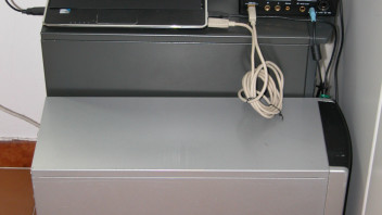
    In an attempt to bring the signal down and check out if the strong short-term variability is due to internal noise, radiations or some sort of external electromagnetic interference, today I added a lot of shielding in the form of old 3.5" hard disks, computer cases, etc around the Geiger counter, not having lead bricks at disposal.


    The GC is in the middle of the black case shown in the photo below, inside a tin-plated steel container, in turn inside a "brick cave" composed of hard disks. Behind the black computer case lie four thin steel layers of 0.4~0.7mm thickness. Having run out of dense materials, The empty space inside the computer case was filled with other material like paper. After I shoot this photo I added another empty computer case to the left, also filled with books/paper.


    The overall signal decreased appreciably, but the general behavior didn't. Since the entire assembly is basically a multi-layer Faraday cage I think it can be relatively safely assumed that external EM interference isn't driving those changes.


    Yet, despite all the effort and having added at least 15 mm of steel (excluding other materials, although it's hard to quantify their actual contribution) on all sides, I could only get on that location to about 50 CPM, from the ~60 CPM I was previously getting with just the static-free wrapping in the 0.75mm copper tube (in turn down from the initial 80-85 CPM when the counter was exposed to the environment in the same location).


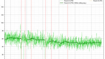
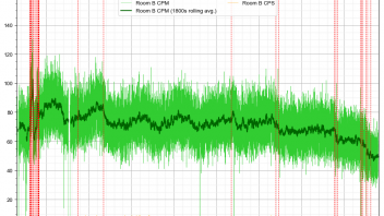
    The noise-like behavior appears to have somewhat decreased, but I'm not sure / not clear yet if proportionally to the decrease in overall signal.


    It would be nice to check out the response with lead bricks of known properties and size, but at an estimated cost of 4-5 euro/Kg in the best case scenario, a suitable brick cave to attenuate most radiations below at least 1500 keV is going to cost a small fortune that would probably be best invested elsewhere.


    I think I'll leave it like this for at least 2 days to check out for the Geiger's long term behavior, then put it out again of the entire assembly and verify that the periodic signal is still there. After that, I think I will be out of ideas for the time being besides doing actual experimentation. The periodic signal still remains a mystery.

    I think most sufficiently thin light materials will be "transparent enough" to X-rays, unless we're dealing with very low energy X-rays, conceivably on the order of 1-2 keV or so, which would need truly special materials to be technically useful as an optically transparent container (unlikely) or as a window component.


    To speed things up a bit since the additional plastic wrapping did not seem to have a very noticeable effect, yesterday I replaced the outer bubble wrap layer with a 0.75mm thick copper pipe I happened to have around. While as expected this caused the overall signal to decrease slightly, it looks like this was a significant contribution to the reduction of its periodic component, which seems to have almost disappeared (this will be clearer in a few days).


    The Geiger counter is located about halfway inside the tube in this photo:


    If real (genuinely due to some sort of ionizing radiation), this should mean that the periodic signal has energies roughly lower than 50 keV, or somewhere slightly above this if including also the thickness of the previously placed plastic wrapping. A 0.75 mm Cu layer attenuates 82% of 50 keV X-rays according to this calculator: https://web-docs.gsi.de/~stoe_…_ray_absorption/index.php


    EDIT: graphs updated

    EDIT: updated again