LDM Member
  • Member since Apr 29th 2017

Posts by LDM

    thank you for your teaching 👍

    A complementary question, how you drive the doping concentration ?

    You have several parameters which influence the level of doping


    Gas flow


    This is how much gas pases throught the reactor at a given time.

    Yhis is normally regulated by mass flow controllers


    Gas pressure


    Some doping can be done at atmospheric pressures.

    Other systems use lower pressures inside the reactor by adding a pump controlled by a pressure sensor.


    Temperature


    Since reaction rate is dependent on temperature, by changing the temperature you can influence the reaction rate


    Plasma


    Creating a plasma inside the reactor will improve the reaction rate.

    It also allows processing at much lower temperatures.

    This can be important for the latest steps, since each step creates a layer with different mechanical properties which can cause stress at higher temperatures, thereby creating defects.

    Therefore on some circuits the latest step of adding a nitride layer is done in a plasma system.

    For how many seconds before the receiver is destroyed?


    I will note again the the mirrors of the commercial device absorb most of the EUV it produces before it gets to the target, because basically everything absorbs EUV

    I don't know what you mean by "the receiver"


    Processing silicon wafers is about changing the electrical characteristics of the silicon by doping.

    This is done in successive steps.

    The first step is applying a thin silicon-oxide layer.

    Then photoresist is put on top of the silicon-oxide.

    Then a light pattern is projected on the photoresist.

    This light can be of different wafelengths, however the shorter wavelengths will allow for smaller dimensions.

    Thus EUV will allow for circuits which have the smallest dimensions or the most advanced IC's.

    The photoresist will be hardened or stay more liquid between the areas where the light was projected and the areas where no light was projected.

    Then the more liquid areas will be chemical removed, this leaves open areas giving access to the silicon oxide.

    Then an acid is used to etch away the silicon-oxide.

    Thus the etching is not by the EUV but by the acid.

    After removing the silicon-oxide layer you now can by diffusion of gases change the electric properties of the underlying silicon.

    The EUV tin plasma machine already exists and is commercially used to etch semiconductor chips. If it made more substantial heat more than the known input then it would be known already, because it uses MW of power.

    The EUV is used to project an UEV light pattern on an UEV sensitive photoresist on top of the chip.

    It is not used to etch the chip.

    Dummy results were 90% of the measured input

    The calculations I showed on this forum showed that for inflated temperatures due to the use of wrong emissivities the result was 86.5% of input.


    For the non inflated case the result was 101.6 % of input.


    An additional check posted on this forum based on a measurement you did showed that the maximum rib temperature must have been near 450 degree C.


    An addition FEM simulation check I did showed me a maximum rib temperature only 0.8 degree C different from the reported maximum temperature.of 461.6 in the report.


    All the above by applying the laws of thermodynamics.

    Subsequent tests indicated these results were wrong. I do not have enough information to judge why that might be. Someone told me they measured emissivity incorrectly. That would explain it.

    No that would not explain it since assuming wrong emissivities goes against what you calculate when applying the laws of thermodynamics..


    That said, I admire all the work you are doing in documenting all the research on LENR.

    Thanks for that !

    Quote from @Jed :


    No, this is not a "judgement call." It is a technical discussion. It must be grounded in the laws of physics and textbooks on calorimetry. No judgement is involved; only facts that have been firmly established for 150 years, and which are the basis of the laws of thermodynamics.


    Then why, if by applying the established methods and theories of thermodynamics it was shown by my calculations that the temperatures of the Lugano dummy run where correct are you still maintaining that they where wrong ?

    You seem only wanting to apply those laws selectively if its suits your opinion.

    So I challange you to consult an expert in heat transfer and prove that my calculations where not correct.

    Alternative way of interfacing the NETIO GC10 geiger counter


    In the past can provided a solution to interface the GC10 geiger counter to a PC by a serial connection.

    The problem to overcome was that the GC10 serial interface uses positive 5 Volt signal levels, which does not conform to the official RS232 serial interface voltage levels which uses both positive and negative voltages.

    can solved this by using an Arduino processor board in order to convert the 5 volt serial signals to the Arduino serial over USB communication channel, the USB then connected to the logging computer.


    While that approach provided a good workable solution, it had some minor drawbacks.


    - The standdard Arduino has both a serial over USB connection and also a 5 volt serial interface, but both can not be used at the same time


    - To solve the above problem, an additional serial port was created in software by using an available software library.


    - Using the software implemented serial port needs programming your Arduino.


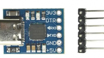
    Needing to set up a serial communication to the GC10, instead of using an Arduino I decided to use a simple 5 volt serial to usb printed wiring board which was designed for use as an Arduino add on. (Some used this kind of solution also for other types of geiger counters)

    This poststamp sized module I used is called the CJMCU CP2102 and is readily available from several sources.


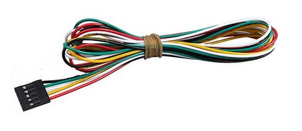
    I did not use the supplied pin header, instead I used a 5 wire interface cable, one end having a female connector for connection to the GC10, the other end being lose wires to be soldered to the CJMCU CP2102 board.


    The following picture shows the connection wiring


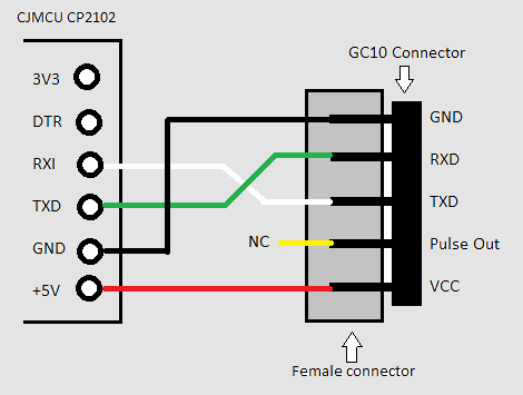
    After making the connection between the GC10 and the CJMCU CP2102 board we can then connect the CJMCU CP2102 board to a PC by an USB cable.

    Power to the CJMCU CP2102 board and the GC10 is then supplied through the USB cable.


    WARNING :

    When powering the GC10 in this way, do not use at the same time the alternate +5V or battery supply connection on the GC10

    The GC10 documentation states that it can damage your GC10.


    After connecting the USB cable to the PC, you can use the assigned virtual serial port on your computer to aquire the data sent by the GC10 or sending commands.

    The silence is baffling... (considering this "independent third-party replication evidence" is available of a claimed direct electrical energy fusion device.)

    LDM, Stevenson, you folks had sharp critical eyes on previous waveforms. Can I ask what would be your take on these results, please?

    I am relative busy trying to help somebody with preparing/doing/commenting on his replication attempts.

    As a result I have not been following this thread in detail, so have currently no comments on your signals.

    That said, if your simulation is a good representation of what your real circuit is, then you can compare the output power of the simulation with the real measured output.

    If the measured output power is significant higher then what is simulated then this might be an indication that you have a COP greater then 1.

    To get your simulation in line with your real circuit you might want to simulate with "real devices" for which the simulation models are often available from the manufacturers. These models often also include parasitics.

    For that your simulation program must be able to import those models. (I use Microcap12, which is free)

    Got yet another explosion, this time with heating resistor. It was ARGOL 10 ohm 25 watt heat sinked resistor, and the problem was that if i tried to go above 200 celcius, there was "explosion", with one cap of the resistor blown out.


    Maybe should try to drill out the center stuff, and use resistor wire, and fill with some non-exploding cement (any suggestions what would be good cement?)


    First of all, the name is ARCOL, not ARGOL as you can see from the text on the resistor.

    But that is the product name, not the brand name which is Ohmite.

    For these type of resistors Ohmite states :


    Heat Dissipation

    Heat dissipation: Whilst the use of proprietary heat sinks

    with lower thermal resistances is acceptable, uprating is not

    recommended. For maximum heat transfer it is recommended

    that a heat sink compound be applied between the resistor

    base and heat sink chassis mounting surface. It is essential that

    the maximum hot spot temperature of 200°C is not exceeded,

    therefore, the resistor must be mounted on a heat sink of

    correct thermal resistance for the power being dissipated


    So it means that if your environment temperature is 200 C, you are not able to dissipate any power in the resistor since that would bring the possible spot temperature above 200 C.and will destruct your resistor.

    If I interpret your scope pictures correctly, then the first high to low transient is about 50 nS and the Voltage step 1750 Volt.

    So your change is 1750/.05 = 35000 V/usec

    Assuming they have exactly the same value, this is 17500 V/usec per capacitor


    The Wima capacitors for 1.5 nF and 2500 Volt are rated for a maximum of 11500 V/usec.

    Could that then maybe the reason why they are failing ?

    Yes - that is why it isn't so crude.


    Try wrapping one plate in plastic, and place the other plate some distance away, but allowing air to circulate around it. What is the voltage between the plates in that situation?

    I covered the lower plate with a tranparant plastic foil.

    No voltage was measured but this was expected since transperant plastic and transperant plastic foils block UVC.

    Conceivably, differential oxidation rates between the two plates (is one on the bench?) could shift sufficient oxygen atoms to create a detectable voltage across your meter. It could become a crude zinc-air battery.

    In a zinc-air battery there is a gel between the electrodes which fascilates the conduction between the plates ehn the gel reacts with air.

    In my set up there is only air between the plates.

    Both plates are indeed zinc plates.

    I know that zinc can be oxidized and indeed at some places I already see some light discolouration.

    However effects on the zinc can only be effective if we have also a conduction (ionization) between the plates

    Note that if air gets ionized, the involved UV energy is at least 15 eV, i.e. far UV under 100 nm. I suggested to use He as a gas, to gauge this energy, since it has an even higher ionization energy, around 23 eV.

    I hypothese a dual effect.

    First the photon energy has to be larger then the work function of the CE.

    If that is the case electrons are emitted by the CE, at least first near the surface.

    Electrons present in a gas will lower the ionization energy needed, so I think energies much lower then 15 eV are then required..


    In my experiments I used a 275nM led with a radiation output of 6 mW.

    (Currently you can also buy 245 nM leds and also more powerfull ones, but did not test those)

    This led has a photon energy of 4.5 eV.

    I started with using brass plates, but since they have a work function of also about 4.5 Ev, no effect was seen.

    So I switched to zinc plates which have a work function of 3.74 eV and then measured a Voltage.

    So it would indeed mean that indeed the electrons lowered the needed ionization energy significantly.


    The effect is repeatable, with the uv led off, I measure a Voltage in the microvolt range, when the led is on much higher voltages are measured, depending on the allignment of the different parts of the test set-up even up to 20 milliVolt.

    Do you surmise that the UV is emitted from the surface of the WE (working electrode) plate? If so, have you tried any way to show those UV rays are present? (e.g. luminous dyes/paint, or phosphorescent crystals?)


    n.b. Sodium salicylate is meant to respond well to UV (even VUV) - and is available on ebay relatively cheaply.

    I indeed hypothise that those photons are generated at the WE.

    However I did not prepare the "WE" and thus did not measure it, the set up was very basic with untreated electrodes.

    Instead I used a deep uv led to generate photon radiation.directed towards the CE.

    This quote is from an Ed Storms email. I think it simple, elegant, and very relevant to what might be happening in the LEC.


    "If... electrons have to assemble around the D nuclei to shield the Coulomb barrier, they would be in contact with the nuclear energy states. When fusion occurs, these states would gain energy. This energy would naturally be communicated to the electron cloud. As a result, the cloud would explode in every direction, thereby carrying the nuclear energy while conserving momentum. Because perhaps a million electrons would be involved, with each carrying only a small fraction of the total emitted energy, the electrons measured by Frank would have only a relatively small amount of energy. In other words, instead of the nuclear product "exploding" as happens when hot fusion occurs, the electron cloud explodes. This is a new and unique feature that is characteristic of this new kind of nuclear interaction. The process is straightforward without the need to propose a complex mechanism."

    If I remember well, Stevenson in his early experiments tested without preloading with hydrogen/deuterium and also the reactor was filled with air.

    Nevertheless there was the voltage effect.

    This likely precludes the theory Ed is proposing.


    I myself hypothised that the LEC might be driven by photons having an energy larger then the work function of the CE.

    My testing was intended to show that high energy photons (deep uv) cause both a voltage difference and also create an ionization path.

    The results show that indeed high energy photons can cause effects as seen in the LEC.