can Verified User
  • Member since Jan 20th 2017

Posts by can

    I realized that spark gap parameters are critical too in the previously linked simulations in that they affect significantly the results, but I'm not sure what would be the best to use. One could make several assumptions:

    • Only arc discharges are produced, which have a very low resistance.
    • Since the arc-discharges are basically produced under contact separation, the breakdown voltage should be very low, somewhat above the power supply voltage.
    • The holding current should probably be rather high, as this is far from being a vacuum environment and the process will be quickly disturbed.


    With something like this (further tweaks might be necessary to On resistance and Holding current) once a large enough current builds up from the power supply interesting arc-discharge trains in the several MHz range appear to be produced, but they could be a simulation artifact (I'm not sure the program is intended to simulate such conditions with the spark gap component). Furthermore real-world conditions will be far from being constant.


    Anyway, bottom line is that it's plausible that the short-circuits will produce noise from the audible to the RF range (EDIT: beyond that normally expected from them as one-off events).


    (Link to the simulation)


    This should probably require a more advanced model and simulator (SPICE-based?), but that would go beyond my basic knowledge of the subject. Here is some background information behind this one.

    Yes, helps clarify the DC behavior of the system. However, it doesn't appear to model the AC behavior of the circuit i.e. the source of the RF signal you detected. Perhaps the simulator has a pulse source available that could be applied to the shorting switch function. Sweeping the pulse rate should show one or more resonant peaks in the waveforms.


    The simulator does have a pulse source. I tried to come up with something acceptable that could work as an equivalent, but I'm not sure if this one would simulate correctly what is going on. You can tweak the parameters, either through the sliders on the right or by double clicking the components. As it is, it doesn't look like it would resonate at very high frequencies, in the RF range, but the equivalent circuit could possibly be improved (the main issue is that it's truly trying to simulate the actual components used, which might not be the best approach here).


    (Link to the simulation)

    (Second version with a shorter simulation timestep)


    To explore the RF behavior, I would like to replicate your cell. Could you please supply some physical dimensions and details of materials used.


    Thanks for attempting to replicate the observations. You should be able to see at least some of them (the non-LENR-related ones).


    The steel electrodes have been selected more or less randomly from a container of steel brackets of various sorts, basing on these criteria:

    • Same overall characteristics for both of them
    • Elongated narrow flat shape
      • Convenient to use in the glass jar I planned employing for the tests.
    • Ferromagnetic properties
      • I thought this would be useful for magnetic field concentration or if I decided to keep the entire assembly together with magnets like I did with the coin and washer combo, which I eventually didn't.
    • Pre-drilled holes
      • I thought this would facilitate the diffusion of electrolyte solution into the narrow gap.
    • Sufficiently large thickness
      • For rigidity and longer lifetime against erosion/corrosion processes.

    The steel brackets I used were initially coated or anodized with some sort of thin (micron-thick) yellowish layer that would appear to react more vigorously in a caustic solution than the steel used for the bulk during the initial electrolytic attempts. I eventually completely removed that with immersion for about 15-20 minutes in liberally diluted ambient-temperature solution of 10% HCl, grocery-store grade. Successive cleaning baths under similar conditions have been performed on different occasions, but that layer was already long gone.


    The initial dimensions for both electrodes were:

    • Width: 14mm
    • Thickness: 2 mm
    • Length: 140 mm

    I don't think that the shape of the electrodes is critical, but I thought that them being thick would help.


    Since the pieces are strongly ferromagnetic and likely of cheap origin, but don't appear to corrode easily, they are probably composed of ferritic stainless steel or some sort of chrome steel. They do not bend very easily, but the thickness might be a factor here.


    On various occasions (typically before a new experiment session began) I used dry 180-grit brown sand paper to roughen their active surface, or the same under wet conditions and less energetically in warm water to clean them up.


    I thought that for this sort of experiments where I'm not specifically using magnets to hold the electrodes together, SS316 (as typically used in HHO cells, by the way) or pieces composed of different materials (e.g. Nickel and Copper, Nickel and Aluminium, etc) could potentially be more useful, especially if electrode polarity is periodically reversed or if AC is used. However I haven't tried that yet and I don't think I have suitable pieces of different materials laying around other than old coins (from various countries).


    The jar used has roughly these dimensions:

    • Inner diameter of top opening: 32 mm
    • Outer diameter at base: 42 mm
    • Height (without lid): 50 mm
    • Capacity: nominally 25 ml

    Feel free to ask for any other detail I might have missed.


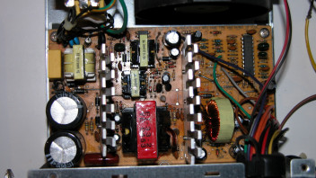
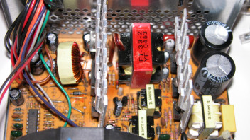
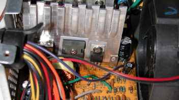
    Because the 1.3 kHz audio modulation might originate in the power supply, it would be helpful to have the make and model for that as well.


    The one I used is a cheap, decade-old chinese ATX 12V power supply normally intended to be used with desktop PCs. It's likely that the output gets dirty when the load is unbalanced, as is the case with many other cheap computer PSU. Close to the current limit of 20A (I'm guessing) at the 12V rail, voltage is not within ATX specifications anymore and drops to about 8.5V, although when such sound was emitted by the cell, PSU did not seem to be close to the limit yet.


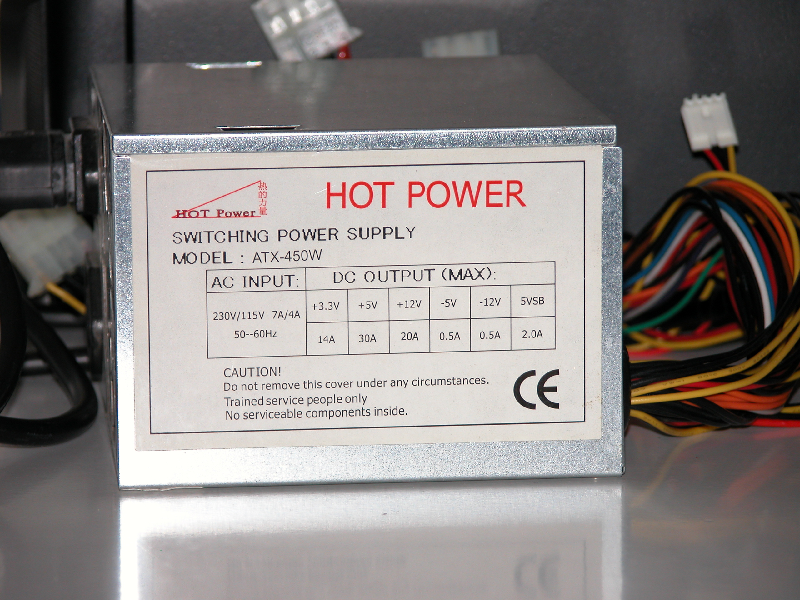
    EDIT: here are a few more photos of the power supply.


    I tried to improve the equivalent circuit simulation of the previously shown setup. The equivalent circuit of the electrode assembly is the square circuit section on the right:


    (Link to the simulation)


    By taking into account:

    • A small gap capacitance of 10uF as suggested by magicsound
    • A significantly smaller coil inductance as suggested by Robert Horst
    • That the gap resistance when a short circuit is not close to occurring is relatively low, rendering the electrode assembly something akin to a leaky capacitor

    It appears that the inductive kickback is not as strong as initially thought. With this simulation it's in the order of a couple hundred volts.


    By disabling the 15 Ohm equivalent gap resistance in the simulation (with the associated "switch") it would be in the order of 3.5 kV and by further removing the equivalent capacitance it would rise to a very brief spike in the order of 23 kV. So these would be the main limiting factors against the generation of very high voltages at the gap.


    Of course, practice will be different than theory and the simulation isn't perfect either. Furthermore this would ignore any LENR or LENR-like phenomena.

    A new, recently published paper from Leif Holmlid. This one is open access.


    * * * * *


    https://doi.org/10.1007/s10876-018-1480-5

    Laser-Induced Nuclear Processes in Ultra-Dense Hydrogen Take Place in Small Non-superfluid HN(0) Clusters


    Abstract: Charged and neutral kaons are formed by impact of pulsed lasers on ultra-dense hydrogen H(0). This superfluid material H(0) consists of clusters of various forms, mainly of the chain-cluster type H2N. Such clusters are not stable above the transition temperature from superfluid to normal matter. In the case studied here, this transition is at 525 K for D(0) on an Ir target, as reported previously. Mesons are formed both below and above this temperature. Thus, the meson formation is not related to the long chain-clusters H2N but to the small non-superfluid cluster types H3(0) and H4(0) which still exist on the target above the transition temperature. The nuclear processes forming the kaons take place in such clusters when they are transferred to the lowest s = 1 state with H–H distance of 0.56 pm. At this short distance, nuclear processes are expected within 1 ns. The superfluid chain-cluster phase probably has no direct importance for the nuclear processes. The clusters where the nuclear processes in H(0) take place are thus quite accurately identified.

    @Director

    Electrolysis here is only a tool to start the arc-discharge process at low voltages. These are not like ordinary cold fusion experiments: the overall average temperature might be lower than 100°C, but locally, when a short-circuit event occurs, it can be in the order of thousands of °C.


    Furthermore, if high energy particles are emitted in the process (including what is recently referred to as "strange radiation"), a large portion of the excess energy produced would probably escape the reaction environment anyway and have to be captured (or using Rossi's lingo, "thermalized") outside of it.

    @Director

    For what it's worth, I might have inadvertently made (and described in the latest comments in the "unconventional electrolysis" thread) a much cheaper/simpler QX knock-off using different techniques and materials. However it does not use Ni-LiH-LiAlH4 (it could probably use Ni and Li in some form, but not LiH or LiAlH4) and it's specifically intended to produce arc discharges in water or a wet aqueous environment at a quick rate, in some ways similarly to Parkhomov's "Woodpecker" device but also extending it in others.


    If you considered this (or similar experiments) a QX-like device, experimentation and perhaps engagement by "replicators" could be much simpler. If you only regard a vacuum tube with Ni, Li and LiAlH4 and "dry" environent as a QX-like device, that puts many constraints on what people might be willing to test and experiment.


    The requirements 1-3 you listed overlap with what I have been tried to do, incidentally. I'm doing the complete opposite of 4. High currents, erosion processes, explosions and discharges do indeed produce pointy tips (although they eventually blow off in my case). Since I have a relatively large electrode surface, many of those will be formed in a way or another.


    This is the main reason why last time I asked if you had a source for the QX being gas-tight. Depending on what you're trying to accomplish in practice, it might not be necessary to have a gas-tight reactor.

    magicsound

    Thanks, nice you found it interesting. Yesterday I was inspired enough to make a sort of infographic about the experiment:


    I've been giving some thought to resonance shown by the radio signal.

    For example, I estimate the capacitance of your electrodes to be about .01 uF. This is based on the following parameters: [...]


    Since under this mode of operation the electrodes would short-circuit quite often I didn't think of them as a capacitor (as opposed for instance to the previous experiment type with coins/washers where I was trying to establish a dielectric oxide layer between them).


    In the past few days with these short-circuiting tests I haven't used any KOH at all. I used milliM-amounts of 10% HCl in distilled water, both grocery-store grade so likely far from being pure.


    The actual coil inductance according to Robert Horst in the comments above could much lower than that; I'm not sure how that would affect your estimations. Earlier I noted that the whine/screeching sound could be heard from the radio at much higher frequency bands in the AM range and even in the FM range (on some empty radio stations), for what's worth.


    I agree that without an oscilloscope it would be difficult to gauge what's going on exactly here. Given the extremely low-budget and improvised nature of these experiments I haven't even conceived the idea of using one.

    As for accuracy, it does help to have a high resolution source image when available, and that it is free of paper or perspective distortion. Manual sampling is an option when automatic recognition fails; that takes much less effort with a pen tablet than with a mouse.

    Robert Horst

    Thanks for your continued suggestions and patience.


    I'll try to summarize what I was trying to accomplish with a few short key points.

    • Originally I was trying to perform electrolysis with a very narrow electrode gap (which motivated this thread).
      • The gap is intended to be in the order of 0.1-0.5 mm or in any case fractions of millimeter.
    • At some point I realized that with a slightly acidic electrolyte solution, material deposition from the anode to the cathode would occur at a quick rate.
      • The deposited particles appeared to be electrically conductive.
    • Since the electrode gap is quite narrow, this condition quickly leads to the electrodes shorting out.
    • When the electrodes short out through the previously formed electrically conductive path, said path vaporizes by the high currents involved.
      • The process causes transient plasma formation, cavitation and ejecta.
    • After a short-circuit event completes, normal electrolysis continues until another short-circuit occurs.
    • A brief amount of time may pass between short-circuit events, and more than one may happen simultaneously at any given time.

    Thus, having observed the above:

    • I was trying to design a very simple circuit which would allow to feed a much larger current to these short-circuit events.
      • The objectives are:
        • Promoting these short-circuit events;
        • Making sure that whenever a short-circuiting path forms it will certainly vaporize.
    • It seems that a large capacitor and few other components might be all that is needed to accomplish this.
      • I haven't fully considered yet personal and equipment safety (last thing I'd want is blowing off equipment, but so far the power supply appears to have resisted abuse quite well).
    • However, since I was using a large coil, currents in the order of several A (possibly up to 20A) and no capacitor, it's likely that not just high currents, but also rather high voltages might have been involved, like the previous "boost" circuit is showing.
      • When a short-circuit blows apart the aforementioned electrically conductive path, the coil's magnetic field will have to dissipate somewhere and this is usually in the form of what I know as inductive kickback.
    • By adding a capacitor to supply larger currents during the short-circuit events, it's likely there will be no inductive kickback anymore.
      • Therefore the nature of what will be occurring in the gap could change compared to what I have been observing so far.
    • However, at the moment, given what other researchers are doing, I'm more interested in providing very large currents (brief peaks of hundreds of A) than intentionally trying to make a high voltage boost circuit.
      • I plan for the time being using readily available 12V DC switching power sources, of which I already have some.

    Robert Horst

    The main function of the coil was (at the time I thought of using it) limiting the speed of current transients at the power supply caused by short-circuit events. These events are desired, but the naive circuit, I am guessing, cannot properly handle them.


    This is probably a clearer equivalent representation of the previous circuit that is more accurate to what I had set up (except the coil inductance which you suggest being too high). 600 mOhm should very roughly be the equivalent resistance of the coil:


    Link to the online simulation


    The above representation however does not simulate appropriately the sudden current interruptions caused by the short-circuits, which in practice appear to cause visible discharges and characteristic noise. I guess in a way these would be similar to some extent to transient spark gaps, which the online application I linked also simulates, but it's not really the same thing (I believe).


    The simulation linked below shows the high voltage kickback from the inductor when current is interrupted.


    Link to the online simulation


    I realize that this is not a current spike though. If I add a capacitor like I did previously, I do get a current spike, but no inductor kickback, so the coil mostly serves to protect (to some extent) and smooth out the power supply there.


    I did consider getting a low ESR capacitor, but didn't think of using a rectifier diode (EDIT: I'd probably have to use several, in retrospect). It would not smooth power delivery from the power supply, but I haven't truly determined if that's actually necessary, so it might turn out to not be needed.


    As for the coil inductance, should I just consider it as an air core?

    This could explain some of the results of these latest tests.


    According to a chemistry book available for reading on this website (DOE-HDBK-1015/1-93, page 117 of the PDF document or CH-02 Page 15) a pH value below 4 for oxygen-rich water is sufficient for increasing the corrosion rate of wetted iron substantially, while one above 10 causes it to decrease until it drops to zero above a pH of 14.


    From Wolfram Alpha it can be easily seen that a 0.1 mM solution of HCl is sufficient to decrease the pH to 4, while the same website puts at 1M the value needed for a KOH solution to reach a value of 14.


    This seems consistent with my previous observations where just wetting the tip of a plastic straw in HCl and bringing it in contact with the 25ml aqueous solution used for the experiment would have been sufficient, especially under electrolytic conditions (where oxygen is directly produced), to increase the corrosion rate of the anode exponentially.


    One could take advantage of this known effect to have an "electrolytically-enhanced corrosion/water arc discharge-cell". If gas evolution is only allowed at the electrode interface, the gap is maintained at a minimal width (ideally, microns/fractions of mm) and load is balanced between both electrodes (either through AC or a slower polarity switching), perhaps electrode wear could be minimal. The plasma reactions would be from short-circuits caused by the material corroding away from the anode electrically connecting both electrodes. Perhaps with carefully sized components one could optimize energy usage and put the inductive high-voltage kick into a specific range that would hopefully be more conducive to LENR.


    If this actually works, it would have the advantage of requiring very simple circuitry and be able to be built with low-voltage components even if the voltages produced at the electrode interface would potentially be high. Or at least, that's what I have in mind.

    After obtaining that the electrodes would often short in a way that would cause a large current draw without the PSU turning off, yesterday evening I stopped the experiment.


    It ran longer than I expected it could, but again no large change was noted at the Geiger counter. Dashed lines in the graph below show started-finished with several pauses inbetween:


    The anode got significantly eroded in the process, while the cathode had for the most part only damage from previous tests with electrode polarity reversed.


    Before and after light scraping and cleaning with just water:


    Main observations

    • Upon inspection, the gap was mostly empty at the end of the experiment just after discharges occurred.
      • This suggests that long loading times/waiting for it to fill up might not be useful. As long as the discharges start occurring, the reaction is ready.
    • A significant amount of particles deposited on the bottom of the jar.
      • This should be consistent with the anode thinning up considerably, but the volume seems large, probably due to water adsorption.
    • Alternating periodically electrode polarity could be useful in evening out electrode wear. Probably better yet, using AC and a cell construction which does not allow a large amount of particles to escape the gap.
    • Anode wear appears to have been the largest on the side which had a slightly shorter gap.
      • Probably consistently with a larger current density on average.
    • Weight measurements
      • Residues 0.25g
      • Cathode 24.62g
      • Anode 22.83g (more than 1 gram lost)
    • The exposed electrode part might be important. Water appears to diffuse there by either evaporation, capillarity or O2-H2 recombination.
    • When the discharges start occurring, water apparently gets consumed very quickly without the large portion of it in the jar actually boiling to a significant extent.
    • The hissing noise appears to be associated with stronger discharges that appear to be more blue in color, occurring above the water level at the wetted but not completely immersed electrode interface.
    • Either the hissing sound itself is headache-inducing or it's associated with the emission of something that causes me a headache
      • When such sound is not occurring no side-effect is felt.
    • If the deposition layer solidifies too much or the resistance increases too much hardly any reaction (discharge) appears to occur, although broadband noise will continue.


    I've made an almost equivalent circuit with Falstad CircuitJS that you can play with following the link


    The push switch on the right is intended to represent when activated the short circuit events. With the capacitor in the middle (not present in the circuit, but is more or less what I planned adding), hundreds of A should be transiently available when such events occur. On the other hand the capacitor will possibly prevent any inductive kickback that might be occurring without it. I'm not an electronics expert however and practice might be much different than simulations. I'd need advice from more competent people in this area.


    15 mH for the coil is an estimation using various online calculators such as this one.


    The coil has roughly 75 turns, 95 mm outer diameter, 45 mm inner diameter, 45 mm height. In absence of a suitable laminated iron core, a bunch of ferromagnetic tools were put in the opening during the test.


    EDIT: here also one more video I made yesterday, showing some of the discharge events until the PSU shut down probably due to excessive current draw.


    https://streamable.com/err6g

    (Link to full-screen version)

    There is also a desktop version of WebPlotDigitizer, but it appears to be a web application and to be functionally the same as the online version:

    https://automeris.io/WebPlotDigitizer/download.html


    Robert Horst

    I found out about it a few years ago. It's still actively developed and it's been used and cited on actual research papers, which I guess gives the program author a moral incentive to continue working on it. I think it's also been cited in some LENR papers (for example here).


    https://scholar.google.com/sch…gitizer&hl=en&as_sdt=0,44


    JedRothwell

    It's possible to sort the data points within the program before exporting.


    Is the RF signal appearing as a discrete signal to the radio i.e can you tune to it? Or does the frequency tuning of the radio make no difference?


    Today I checked again with the cleared/cleaned electrodes and to my surprise the frequency band does not make much difference to the hissing sound. This means that at higher frequency the hissing sound is more isolated from the broadband white noise also associated with a running experiment. For what's worth, I had the impression that at higher frequencies on the AM band it would be very slightly stronger around 1000 kHz on the dial (i.e. 1 MHz). I also tried FM and I could hear it there too sometimes, but there was competing "interference" from broadcasting radio stations. I found a very narrow spot around 100 MHz where I could isolate it from them.


    I've made a couple more videos earlier. The radio was not running, so the sound should be that emitted by the jar alone. Sometimes the hissing sound would kind of "breathe". Sometimes in addition to orange-red discharges, blue-colored discharges would be visible as well. In some instances incandescent sparks would get emitted from the exposed portions of the electrodes.


    https://streamable.com/oocvj

    (Link)


    https://streamable.com/kwjio

    (Link)


    I don't know if it's just a psychosomatic reaction due to it being the 11th most annoying sound in the world, but the hissing sound when present (sometimes it disappears. It seems to be correlated with how intense the reaction is) would cause a short-term slight headache. It's possible that some harmful chemical is being produced. No difficulties breathing or coughing sensation on the other hand (e.g. from the HCl, of which however I just use traces).


    At the moment the jar is turned off. While today it behaved more reliably than it did yesterday (yet sometimes causing the PSU to shut down) I still wouldn't trust running it unattended.

    Bruce__H

    I'm glad you appreciated the effort, but please also check the original document to make sure that the values are correct, because I transcribed it in 30 minutes or so and it likely contains errors and certainly a few placeholder words where I couldn't figure out LION's writing at the time of reading.

    As expected, the deposited particles scraped out of the internal walls of the electrode gap with a piece of paper are strongly ferromagnetic. They have a dull dark brown appearance and easily stain the surfaces they come in contact with. My precision scale isn't super accurate, but it appears that this much amount of material is about 0.08-0.10g.


    I think the electrode assembly could be reused as it is now that it's been cleared and dried. While this is also thanks to the wide gap, ideally it would be much narrower than it is now, even if it becomes narrower during operation. That would allow for quicker operation and lower amounts of HCl initially required to start the process.


    A few days ago I learned that while in theory distilled water (which is what I initially used) has a pH of 7.0, in practice as it absorbs CO2 from the atmosphere it decreases to about 5.5~5.8 . To hasten this change I initially injected ambient air into the water with a small manual pump. From there, bringing in contact the tip of a plastic straw wetted with 10% HCl solution with a wet part of the electrode assembly (in 25 ml of water) would be sufficient to start the rapid deposition effect I observed.

    I'm not entirely sure if that was due to the change in pH down to a lower threshold level, or merely due to introducing HCl.

    magicsound

    The screeching noise/signal was a new and unexpected feature and I forgot to check out if the radio it could be tuned to it, but an associated noise that I often observed under similar conditions (without the coil) that could be best described as a broadband noise (static) with the characteristic of ramping up in magnitude the closer the PSU was to short out (or in other words, the closer the electrode gap was to get filled with material and reaching a point where it would form a stable conduction path), appeared to be best heard at the lowest selectable AM frequency band of 530 kHz.


    Sometimes it would be irregular, others it would have a more continuous nature. A few days ago I made a recording of the former:


    https://streamable.com/n5of7

    (Link)


    At times it looked like reversing electrode polarity once would immediately trigger the latter, so as of today I'm still not completely sure if it's 100% due to short-circuit/discharge events.

    Wyttenbach

    Admittedly, these tests are more like a "shotgun" approach. If any anomalous effect will occur it will be due to the extremely variable and random conditions rather than precise tuning of the operating parameters.


    magicsound

    You can find attached the raw audio from the original video for more accurate analysis. The video hoster Streamable appears to degrade audio quality considerably. Keep in mind though that the AM radio in that video was also turned on and it emitted a similar noise to the one physically coming from the jar.


    I never heard that noise before installing in series the coil, so it's possible it could have been caused by it. Without the coil I could never run it semi-reliably in this mode.


    Shane D.

    It was indeed quite annoying and headache-inducing (hopefully not caused by anything else emitted from the experiment).

    Unfortunately I ended up spilling the contents of the jar due to the unbalanced weight of the electrodes and the test had to end.


    Even with the larger gap (slightly less than 1mm) I have problems with the PSU voltage sagging and not providing enough power to vaporize the some of the thicker conducting pathways forming between both electrodes, so eventually it either shuts down due to triggering its overload protections or overheats the wires without being able to restore impulsive conduction (mixed electrolysis-arc discharge?) status.


    I haven't been able to observe any large and/or short term increase that could be associated with the ongoing reactions, but coincidentally CPM appeared to decrease twice as I started the experiment initially and as I added a tiny drop of HCl (first and second dashed lines). However it's too easy to read too much into these minute variations. The third dashed line denotes when I ended the tests, which haven't been continuously performed due to PSU issues. So, overall no significant change appears to have occurred.


    Still, I think if improved this could have some potential to show interesting results.


    EDIT: earlier I forgot to post this video which better demonstrates the screeching noise I was mentioning about:


    https://streamable.com/ycfht