
!http://www.rexresearch.com/ehrenhaf/ehrenhaf.htm I need to read this a few more time and see what some of the words mean but this is close
Protons electrons ect.
-
-
Clayton,
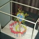
First Wow! I saw your "gizmo" I remembered it. I see so much stuff. That you made this is just cool. But is this a model of what you trying to do or do you have another sketch? Even by hand. What do you call it (anything I do not know the name of is a gizmo). And respect that you made it. Let me know more and I will write shorter posts with more links.
What are you trying to prove with levatition? and why the maggie? exactly why this time. -

Not the video you mention, but the work on magnetic vortices sounds very like that of Felix Ehrenhaft. Now you have the name maybe you can find what you want?
External Content youtu.beContent embedded from external sources will not be displayed without your consent.Through the activation of external content, you agree that personal data may be transferred to third party platforms. We have provided more information on this in our privacy policy. -
Clayton,
Axil posted the original video, I had forgotten that... hat tip to Axil. I opened the video on youtube and went thought the video comments to see why the test in the video failed. I can not find the specific comment you should look for as it is buried several pages deep. One specific comment may help was the daniel nunez youtube channel or Rodin coils. I also recommend reading and googling what Alan Smith wrote. He is an experimenter, not quite a good ole southern boy from the bay area in Maryland But he is hands on.
I always follow Axil he is educational and like Alan are always trying to help.I know that you are looking at maggies and not electromagnets per se. I keep going back to this for a reason. You need to model something, think of this as visual modeling just to give you an idea. As people read this thread they will chip in. Once you model your flux you will may get a better idea on HV you need to go. And different coil windings. And if you go HV on the cheap for your idea, better stockup on old tube TVs, save some money. If you go with a low power low flux you may want multiple maggies. But to get HV parts you old appliances that have these circuits, it can be a time saver. Good luck.
-

Clayton,
Axil posted the original video, I had forgotten that... hat tip to Axil. I opened the video on youtube and went thought the video comments to see why the test in the video failed. I can not find the specific comment you should look for as it is buried several pages deep. One specific comment may help was the daniel nunez youtube channel or Rodin coils. I also recommend reading and googling what Alan Smith wrote. He is an experimenter, not quite a good ole southern boy from the bay area in Maryland But he is hands on.
I always follow Axil he is educational and like Alan are always trying to help.I know that you are looking at maggies and not electromagnets per se. I keep going back to this for a reason. You need to model something, think of this as visual modeling just to give you an idea. As people read this thread they will chip in. Once you model your flux you will may get a better idea on HV you need to go. And different coil windings. And if you go HV on the cheap for your idea, better stockup on old tube TVs, save some money. If you go with a low power low flux you may want multiple maggies. But to get HV parts you old appliances that have these circuits, it can be a time saver. Good luck.
Russ Gries ran experiments to test if the Rodin coil produced a anisotropic magnetic field. The Rosin coil does not work. Use rare earth magnets if you can.
-
Let me get the reading done and get my note together and I will set up more details.
This will take some time -
I ran into this video last night
Time stamp 9.28 Is a good view of what I see this thing is doing at the plate area.External Content www.youtube.comContent embedded from external sources will not be displayed without your consent.Through the activation of external content, you agree that personal data may be transferred to third party platforms. We have provided more information on this in our privacy policy. -
I opened the video linked in youtube so I could see the authors channel and the comments. I have heard of him before. My personal take is not that you can believe everything he says as "gospel", but me neither
. Anyway this is the nature of a strongly opinionated person. They are passionate. What I like is that he is visually modeling the flux and using animated tools to simulate the torus.I have a bit of a background in sims and modelling but now it is almost historic. But one thing I learned no matter how strong your theory, to try to visualize (model) before you build. Of course people were paying me to model as the science/theory part was done. They were looking for best design. Your idea is part of a design, so try to flesh out the other parts. Question yourself on how the build materials will react, how the fields will react, how strong a flux is needed, how fast does it need to switch, how much voltage will levitate a 20 micron particle, then 10 of them. Write it all down, make sure each and every idea is clear to you. Then ask someone else if it is clear to them (kinda what you are doing now). Get some iron powder and play with the flux around a magnet. Doughnet torus is a valid design but may be unstable at low voltage levels, regardless. So review your design voltage wise. After all having a beautiful torus that will not support your POC will just lead to redesign and frustration. The device that the YT poster used to show flux would be worth looking into. You will need a way to clearly show the device is working. I mentioned water as it will separate your "dust" particles. Regardless of if you put the gizmo in a glass box you may get thermals from the maggie.Or the field may have a weak spot in one area. Expect that small granulated particles will clump together. This will need to be addressed. While you have an interesting coil, review different coil winding designs incase you need to reinforce your fields. I had forgot to ask, what is the reasoning behind the stacks in your pic?
-
Think of the stacks as a vacuum , each has a step up and will pull inwards. It will keep the dust from sticking
More.
A few rules I committed to early in this..
The device needs to discharge atleast a little bit all the time to keep it from callapsing the magnetic field. I think it needs a constant loss or negative
back to itself to keep the cycling to continue. It is something that I keep in the back of my head at all times. This is why I don't think certin things like
rare earth magnets will work, they will not change it's strength as the devise powers up. I'm committed to this, "OCD style". It will be hard to get this out of
my head. Anything within the design will need to change as the discharge increases or decreases.
It will automatically change the the pulse rate during discharge.This is how I stear myself through the information that I am looking for.
Yes, I feel a little relieved which is why I fell asleep after I read an replied this morning.All of this is from early tests I did to understand why I'm sure of what this thing is.
This is how I have been thinking this out. I first magnetron that I posted was an odd design and they picked it out immediately.
As I looked at and then cleaned up the black and white silhouette, it was easy to see what it was then I built it from the raw design. The only thought that I had
while looking at it was that this design had 3 different types of cavities. One excelerates, one circulates and one will bounce. This makes me think it's not about
power as much as maybe it's about sound or a chord type wave or maybe a carrier to piggy back a specific element. This thing has drug me all the way into string
theory reading on how it may be seperating parts from an electron or something within the elements "but now I'm reaching".I'm just building it part by part.
Now I am thinking of it as taking a tiny amount from millions of pieces, that is how I concluded that dust was the main moving element as a carrier.
Now you are talking about creating a magnetic bubble around a tiny dust partical of gold as a particle carrier for ????The part with all the wire posted is just one of four. This thing cannot make power, it is more like a ??? I don't know what to call it yet.
It will need a power plant to power the caths, another one to feed the magnet coils and one more to recical the dischage I think it needs to keep running and all of
it needs to stay in a cycling phase pulse so it will not calapse. " It will not turn off if it starts...."I think I have a grip on the parts but not beyound the fundumentals.
This is where the coincidences start and how I got some of the parts to fit and why I think it works like this, But.. I would prefer to build them to show you.
I will add as I get each part done.
It will just takes time.
t -
Best I can do for now.
pc2
The right hand rule in place If you look at a heat elmt for a stove its no the same. its its another hint its about an orbit -
Clayton,
I am misunderstanding your analogy, so I think you mean you expect the
“stacks like a vacuum” statement to mean sucking and pulling
the dust away? This makes no sense to me. Please explain? You
expect this to work like a torus that is pulsing as required? Please
explain? The dust you reference (is it Fe? Or a composite?) Need to
know your dust composition.You did early tests? Not sure how they came out so more info needed.
Good/bad or in between?The device discharging all the time can be handled by a cap or a circuit with diodes blah blah blah.
It may need a timer so that needs to be addressed. A cap in a normal
digital circuit will collect static charge then discharge as
required. But it really is almost steady as it needs be to keep the
more sensitive devices like hungry circuits that require steady voltage happy. This is beyond
this post and will head to schematics. A transformer and a cap alone
will not work IMO I really mean, it will not even be close to working . If you see a circuit diagram it can look like it
is all one jumble. This is not the case. It has breaks for example
using caps or diodes and can be isolated or in a branch. Schematics
are labeled as such. The symbols are just ways of making words visual
and are standard and universal. I do not know if this explanation works for you. So
it may come off sounding like “Duh” I do not mean it this way.Your design cavity is valid (as you say there are many types) but will
not produce any where near the flux in the video you refrenced. But
this is based on my current understanding of your “GIZMO”
hence called “gizzy” unless you state otherwise. We gotta call
it somethingI am also what not sure what"it will not turn off means". It has to start, and it
will stop eventually. So these are separate and must be addressed.Coming home to a cooked circuit smells bad and your wife will
complain. Especially after you get 20,000 volts a a few milliamps
(joke here). She will be done with this. If my wife smells ozone in
the house, she can be quite terse. And she does not want to hear it. And she hates old TVs in the basement (no joke).Some terms you may have heard about resonance, when you hit a bell you
have resonance. There is a word used call Q. High Q is good, but if
you grab the bell its called then called dampened. There is a great video on
using tuning 2 separate tuning forks by Walter Levin (MIT) I am not
sure I can find it but google this name I think the course number is
803 and find resonance. It is a visual that will explain Q (this is
your holy grail so worth understanding) It maybe lesson 4 (or not) anyway he hits the
turning fork on his left side, two feet away is a separate but equal
looking tuning fork, once resonance happens the separate by 2 foot
tuning fork starts to ring. I need to say this now. I do not assume anything about people you
included. I can talk about how circuits are designed but if you need
more or less explanation I would not be able to tell or even guess. It is
not how I think, anyway I will be gone for a day or so. Good luck. -
For a 'dusty vortex' look at cyclone technology, as used for dust separation in industry. It is a fascinating topic in itself, and has from time to time been mentioned in the context of energy sources. Also the work of V. Schaumberger in 1930's Germany may offer some valuable insights - see RexResearch for that man.
-
I never would have found all this .. Thank you ...This should get interesting
I will start adding parts pic with the "my thinking" in raw form.
I'm going to use word like AC Wave timeline singwave ect.Please dont think its what will be used. Its just the best way I know what to call it.
I also dont know if this 1st plate needs to be clockwise or counter clockwise as it takes a hit," pulse".
The Shaft in the center is a outboard lower unit likly 4130 chrome moly solid shaft, It should take a good hit without melting.
The spiraling plate takes a hit at the outside edge from a negative low static "like charge" and should run through the plate to the positvely charged moly shaft center post.
Now add a 100 more plates decreasing in size 1/4" at the feed wire end of the spiral to the solid shaft inside " the hunderd wires in the pic".
Each plate is hit with the small static charge in a 1 2 3 through 100 in a sequence creating what I'm calling the "vacuum pump" or a vorticity like tornado of low power static charge jumps from the negative charged outer plates insulated from each other to the positive charged solid core. .040 gap -
Display More
I never would have found all this .. Thank you ...This should get interesting
I will start adding parts pic with the "my thinking" in raw form.
I'm going to use word like AC Wave timeline singwave ect.Please dont think its what will be used. Its just the best way I know what to call it.
I also dont know if this 1st plate needs to be clockwise or counter clockwise as it takes a hit," pulse".
The Shaft in the center is a outboard lower unit likly 4130 chrome moly solid shaft, It should take a good hit without melting.
The spiraling plate takes a hit at the outside edge from a negative low static "like charge" and should run through the plate to the positvely charged moly shaft center post.
Now add a 100 more plates decreasing in size 1/4" at the feed wire end of the spiral to the solid shaft inside " the hunderd wires in the pic".
Each plate is hit with the small static charge in a 1 2 3 through 100 in a sequence creating what I'm calling the "vacuum pump" or a vorticity like tornado of low power static charge jumps from the negative charged outer plates insulated from each other to the positive charged solid core. .040 gapI beleive that what you are trying to get to is being developed by Harvey Norris
I received a post on vortex showing his latest work, a resonant EMF based energy amplifier. I don't understand it. you might... It is suppose to convert time into EMF energy. Norris has a collection of videos that shows his development process.
QuoteDisplay MorePioneering the Applications of Interphasal Resonances http://tech.groups.yahoo.com/group/teslafy/
On Friday, December 2, 2016 9:06 PM, "[email protected] [teslafy]" <[email protected]> wrote:
In this video I look at establishing standards for historical records concerning time distortion measurements of the operating device. I see that the primary time is compressed by 4/5ths and can show records from the video later on. Efficiency measurements can also be deduced by adding the squares of all three primary voltages; multiplying that sum by the 272/1 ratio between primary and secondary capacitive values; and then comparing that value to the sum of the squares of the secondary voltages themselves. Each secondary oscillates a 6850 ohm 50 nf capacity at this freq of 465 hz. equating each ma of conduction to 6.85 volts. Problematic in the video is the fact that on the close looped bulb observation the discharges are not steady at all as in the polar case. This is remedied by a 4.2 nf air capacitive midpoint ballasting to be shown in the next historical video. Then a realistic efficiency for commercial application of the system can be formulated. HDN
External Content youtu.beContent embedded from external sources will not be displayed without your consent.Through the activation of external content, you agree that personal data may be transferred to third party platforms. We have provided more information on this in our privacy policy.__._,_.___
Posted by: [email protected]
-
Its a lot like looking at the hutchinson effect videos, I'm to new at this to understand it without starting at the first step but thank you for posting it.
I will look over the whole design as I take brakes. Wife pushed me out of the house into my trailer lol no internet... -
Is V Schaumberger a book? I cant find anything.
-
Sorry Clayton, my mistake. It is Schauberger, no 'M' in the middle. Here's a video introduction.
External Content www.youtube.comContent embedded from external sources will not be displayed without your consent.Through the activation of external content, you agree that personal data may be transferred to third party platforms. We have provided more information on this in our privacy policy. -
Thats kinda funny... I build a flying v type toy years ago because of this video lol I did not exspect to ever see it again lol
Same theory
Do you know of anything more up to date work on Felix Ehrenhaft type work but without light? -
I have just the thing to mount your wing on. A kit car I built when young. Had 225 aluminum V8.
-
Do you know of anything more up to date work on Felix Ehrenhaft type work but without light?
Have a poodle through the papers of Harold Aspden. All freely available on line. http://www.haroldaspden.com/
ETA- contains links to a couple of his LENR type patents - and much of the tale of his battles with the USPTO.


