can Verified User
  • Member since Jan 20th 2017

Posts by can

    magicsound

    To further clarify the underlying idea, the experiment was devised so that slight amounts of water (electrolyte) could be introduced from the opening on the top electrode and diffuse evenly through the gap, which surprisingly it generally did. So it was convenient that the bottom electrode was larger than the top (that coin is pretty large with a ~28 mm diameter), that the top electrode had a hole in the center and that they were both disk-shaped.


    Since I don't have suitable equipment to make clean holes through hard alloys, a coin and a washer conveniently worked as the materials for the experiment. That they are both ferromagnetic incidentally made it easier to hold everything more or less together with a relatively strong magnet.


    In a more professionally done experiment with the same "semi-wet" concept, larger sheets would be more convenient to use and allow to clamp everything together firmly in place. With square or rectangular sheets however there might have to be several openings for the water or electrolyte to diffuse properly everywhere.


    Today I attempted an experiment with "wet" electrode plates of unknown steel alloy (still ferromagnetic) similar to another I described earlier in this thread, again with minimal gap. It appears that at a high current with the electrodes very close together there is minimal oxidation at the anode, which remains clean (and even gets cleaner in the process), while the cathode becomes black (this is what i used to observe in the tests described in the opening post). What looks like cavitation damage is visible at the inner surface of the anode.


    EDIT: attached experiment notes and observations (WIP); the document also contains other photos.

    From an online description, I think the 100-lire coin is made from Cu-Ni coinage alloy of around 70% Cu / 30% Ni. The ferritic stainless steel alloy composition is unknown but would typically be at least 82% Fe (430 Alloy).


    Now I see why you mentioned Cu-Ni. It looks like the one you linked was a newer series.


    This is the coin I used, quoted from the same website to be composed of stainless steel:

    https://www.leftovercurrency.c…-coin-minerva-large-type/


    EDIT: I probably wouldn't have used the other coin type because it would have not been as large as I needed and I wanted to have mainly Fe-Cr-K oxides at the coin interface without involving significant amounts of other elements.

    magicsound

    Pre-WW2 100-lire coins indeed contained Nickel, but later ones didn't (EDIT: this is not entirely correct, see next comment for clarification). The earlier version was composed of an alloy equivalent to SS302, while the latter to SS430.


    https://en.wikipedia.org/wiki/Acmonital

    https://it.wikipedia.org/wiki/Acmonital (contains more information, in Italian)

    https://www.lamoneta.it/topic/…=comments#comment-1092380 (background, in Italian)


    Following the previous post I did more testing and indeed as Alan Smith suggested it seems that the assembly (also) acts as a capacitor, especially when the electrolyte solution has dried up (and the oxide layer/dielectric acts more as an insulator). So, in some ways this worked a bit like a partially self-recharging, battery-capacitor hybrid (if this makes any sense).


    At some point I tested also the voltage-resistance behavior (to the extent of what was possible with my equipment) and it looked as if the higher the voltage the higher the resistance, which seemed to suggest a capacitor-like behavior (larger separation -> larger resistance?).


    Unfortunately no real signal that could be clearly associated with the testing was measured at the Geiger counter located about 2.5-3 meters away. I'm still getting a periodic signal but no long term increase that could be indicative of some sort of activation of materials nearby. It's difficult to make out whether the smaller features are real or just noise.
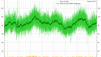


    (the brief spike on the left was when I tried placing the canisters of K electrolyte close to the Geiger counter)


    A final test yesterday was using much larger amounts of (supersaturated) electrolyte in an attempt to replicate the methods used for the first tests (before I made this thread). I used K2CO3 instead of KOH (safer to use liberally) and I found that growing a thicker red iron oxide layer would be much easier this way. On one instance I observed a sort of heat burst, but that could have been due to higher current being passed through the thicker porous oxide layer formed without shorting the electrodes out. I'm not measuring temperatures yet, so this is just a subjective observation.


    (a thick, iron oxide-potassium carbonate dried "paste" is visible in the second photo, it's not just rust)


    I couldn't reproduce the grainy black layer of the opening post, which at this point might have been due to bicarbonate impurities left in my DIY sodium carbonate. It seems that electrolysis of NaHCO3 gives of carbon monoxide, a notoriously powerful reductant (source).


    A better idea would probably be forming such layer beforehand (possibly with other methods) rather than growing it on the spot with the electrodes on top of each other. Improvements would be also needed in order to apply a large current in a way that the magnetic field generated won't make the electrodes slide against each other (destroying the intermediate layer).


    In the end after not seeing any improvement (mainly due to brittleness of the oxide layer formed, even with K2CO3) and continuous attention needed and difficulties to making it work as intended, yesterday I teared the setup apart. The electrodes are still on the low-temperature heater slowly rusting away together with other pieces.


    Today I started a new one with slightly different materials and arrangement, but still with ferromagnetic steel and still in a sense "unconventional electrolysis", but more on this later.

    Alan Smith

    It's going to rain for the next couple days and it has been raining for a while at my location. I've been using only moderate artificial light for the past day or so. However the electrodes are currently in a low temperature heater held at slightly above ambient temperature (around 45°C, I think). Not much of the already dim artificial light makes it there, but I guess that infrared radiation could also be considered light.


    From the graph I posted above it appears to go from 0 to 380 mV in about 90 seconds, no need to wait for hours. This wasn't clear from the thumbnail, so I'm posting the full graph below.


    6793-unconv-electrolysis-20181125-self-charging-curve-png


    And here is the source video. Here the electrodes were over the low-temp heater but not with the DIY infrared reflector in place:


    https://streamable.com/u19ke


    Over the course of about 60 minutes it will reach roughly 480 mV as long as the electrolyte doesn't completely evaporate (just traces seem sufficient) and the electrodes don't short.


    Adding more electrolyte causes a temporary slight voltage reduction (e.g. from 472 mV to 444 mV) but then it recovers. If I add distilled water, voltage decreases significantly.

    Alan Smith

    The behavior reminds me of that of a "dead" battery in that it will maintain a baseline voltage level and even slowly self-charge to some extent, presumably due to ongoing chemical reactions occurring within it. Don't capacitors discharge to 0V? (not that I have any real experience with their charge/discharge curves. I looked at diagrams on the internet and thought that batteries were closer in behavior)


    Earlier today I inadvertently displaced the top electrode, which caused it to short and lose its charge. After that moved it back into a correct non-shorting position and added KOH electrolyte, but didn't attempt to charge it up. Voltage over time went like this (spot measurements):


    EDIT: I made another test after short-circuiting the electrodes.


    I found (not that much of a discovery since it should be expected) that the electrode assembly would work as a very leaky battery. At 5V it can be charged to somewhere above 2.5V, which quickly drop below 1.5V within a couple seconds, then it follows a discharge curve similar to this one I recorded earlier with a webcam and a multimeter:


    So I can imagine that the full discharge curve would be similar (on a much shorter term) to the typical ones for ordinary batteries and that the sharp drop on the above graph would be right after where normally batteries would be considered discharged:


    Which made me realize that if this was a real functioning LENR cell, then the operating conditions would be akin to those of an abused rechargeable battery (overcharging/overdischarging, possibly cycling back and forth between these states).

    Alan Smith

    Of course I was not expecting immediate results. There is certainly an enjoyable aspect to the testing, but at this level it's almost similar to gambling in many ways.


    Right now I'm keeping the previously treated electrodes on a very mildly heated plate, adding distilled water or KOH solution as the solution dries up and the electrodes seemingly slowly rust away (I guess some hydrogen must also be evolved in the process?).


    Coincidentally over the past day I've obtained the highest and most prolonged "background" peak over the past few days and certainly noticeably higher than it was yesterday even just after bringing the K electrolyte canisters in the testing room at about the same time of the day. Furthermore in some cases it seems as if after adding water electrolyte solution briefly increases short-term readings.


    All of this could of course be wishful thinking (i.e. previously mentioned the gambling factor); it's too easy to see patterns where there probably aren't.


    With the electrodes unpowered, after adding KOH solution, there appears to be a 300-325 mV voltage between them, with the top plate (which incidentally uses to be the cathode during active testing) at a negative voltage relative to the other. Galvanic corrosion should be occurring at some level.


    DnG

    The graphs at the end of the document are certainly interesting. HCl even at only 10% wt. concentration (grocery-store/cleaning grade) is a better electrolyte than I imagined.


    (etc.)

    Alan Smith

    To clarify I wasn't blaming you for the apparent lack of results with it; I planned getting one and/or the other at some point anyway (and the canisters also work better as a check source than bananas).


    On theoretical grounds KOH should be better than other choices as an electrolyte; for the same reason it's most often used in alkaline batteries and indeed I think was getting a higher than usual power supply load with it (a proxy for current until I get a suitable current clamp, which I should as soon as I can). As for whether I am getting higher temperatures for the same current, that's something I can't verify yet with my "setup".


    EDIT: here's an interesting document on the conductance of various chemicals https://www.emerson.com/docume…ed-chemicals-en-68896.pdf

    I did a test with KOH but I haven't noticed anything noteworthy yet (EDIT: other than it's crucial that an oxide layer forms between both electrodes in order for this kind of experiment to work). Due to possible immediate hazards I used limited amounts of it at a time, however. Also, the Geiger counter is still a few meters away since there I have weeks worth of data, and I am looking if there's anything that is increasing background measurements anyway, not trying to measure local gamma spikes. Notes and photos under the spoiler tag below.


    My suggestion (after a quick read of your very comprehensive notes) is to try potassium hydroxide. Just a hunch.


    Can you now reveal what was your hunch based on?


    I received the potassium electrolytes, which came with a chemical analysis sheet.


    KOH

    Potassium Hydroxide flakes - KOH 90% 1 Kg


    Parameter Value Tolerance ± UM Method
    Appearance Flakes
    Concentration 90 Minimum % ASTM E291-86
    Chlorides (KCl) 100 Maximum ppm ASTM E291-86
    Iron (Fe) 15 Maximum ppm ASTM E291-86
    Sodium (NaOH) 1 Maximum %p. ISO 1550-73
    Nickel (Ni) 5 Maximum ppm ME 26011
    Carbonates (K2CO3) 0.5 Maximum %w. ASTM E291-86
    Sulphates (K2SO4) 20 Maximum ppm ASTM E291-86
    Silicates (SiO2) 50 Maximum ppm ISO 995-75


    K2CO3

    Potassium carbonate - 1 Kg can


    Parameter Value Tolerance ± UM
    Total alkalinity (K2CO3) 99.5 Minimum %w.
    Free potash (KOH) 0.2 Maximum %w.
    Sodium (Na) 0.5 Maximum %w.
    Humidity (H2O) 0.5 Maximum %w.
    Chlorides (Cl) 30 Maximum ppm
    Iron (Fe) 2 Maximum ppm
    Insoluble in water 100 Maximum ppm
    Density, at 20°C 1.300 Typical Kg/l


    To put radiation-related issues back into perspective, I tried placing the bottles close to the Geiger counter for a few minutes, from which I logged these changes (due to Potassium-40 radioactivity). First with one bottle (KOH), then with both.


    Alan Smith

    Ideally one would need to know in advance which ones offer such relatively easy way to get temperature values as in the link above. I suspect many of the cheap models I have considered getting might not have such guarantees. Thanks for the possible suggestion, though; worth considering when I'll decide to also get an Arduino or similar experimental board to play with.

    Alan Smith

    I don't have any real reason to wait for photos, just a few words would be fine.


    I'm mostly curious because all affordable IR probes I've come across recently don't seem to have data logging capabilities or USB output and I was interested in getting one for quick tests (with all possible caveats considered due to emissivity issues, etc). If I have to spend in the few hundred euro range just to have this feature which could be very cheaply added by the manufacturer, then the money will be most probably be better spent elsewhere, at least on my part.

    @JohnyFive

    What brand/model is your IR gun? I am interested in one that can be used for both measuring and logging temperatures like yours.


    No, not too difficult to replicate, but all it would show is that electrolysis changes the infrared emissivity of the stainless steel plates. That would result from the color and texture change change commonly seen in electrolytic treatment of metals.


    I was looking at the previously described excess heat experiment again. A broad, far infrared light source is used. What about putting the plates into separate metallic containers/enclosures having the same size and surface texture, and then heating the containers with the same heat source? If there is a genuine temperature increase caused by a reaction on the surface of the treated plate, the container that includes such plate should heat up more.


    The containers (or at least the control container) would have to be heated to about 250°C so that they themselves become far infrared emitters (not only to the outside but to their interior too).


    Would this procedure avoid issues with plate emissivity or bring other ones? (Or even work at all)


    (EDIT: perhaps in the most basic form the container/enclosure can be just Al foil wrapping and the heat source a large heated pan/heat spreader or an oven)


    Good catch. That is interesting. Hopefully Simon breaks his silence to tell us a bit more about what ill effects he experienced, what he attributes it too, and what he is doing to prevent it from happening again. Others doing the work need to know these things.


    There is a contact form on the main page of his website, perhaps he also reads messages there?

    The same page I previously linked has had another update a couple days ago, but not with more information about the effects he experienced.

    After a few more days of testing I could not obtain any clear indication yet that the previous experiments have been increasing the background radiation level.


    I tried making a graph with a 24-hours rolling average of Geiger counter readings of the past 10 days or so to better show the long term trend and remove the 24-periodic signal. There was a kind of stepwise increase a few days ago, but it didn't increase anymore after that. The location of the counter has remained the same all along, except for a few checks after which the location was restored to its original place, returning short term readings to their prior values.


    For the sake of completeness (and to some extent, transparency), attached is a document with all the notes from the tests I've done so far in the previous days under the common theme of not immersing the electrodes in water, but just providing water/electrolyte solution as needed. I acknowledge that the tests are very crudely done.


    I'll continue similar testing after obtaining KOH and K2CO3, which might be either later today or next Monday.

    I wonder if JohnyFive is obtaining a figure of 1.2 by doing something like:


    Σ(T_Active4) / Σ(T_Null4)


    In this way (using Kelvin temperatures) I'm obtaining 1.22


    That's basically pretending that the temperature recorded is an average value for the entire reactor in order to integrate the pseudo-power/energy obtained for every second in the data with its fourth power.

    gerold.s

    Rather than energy calculations (which I have not attempted at all) my graph was intended for better understanding what might have possibly occurred in the reactor. I was curious myself and I shared the result in this thread.

    @Director

    I think BLP are simply pulsing current on-off into the arc regime to avoid quickly self-destructing the apparatus. It would probably be difficult for them to have any sort of controlled glow discharge due to the solid metal particles suspended in the environment and the fact that they generally use pressures around atmospheric, not a moderate vacuum (mTorr-a few Torr range) as the Correas describe in their patent applications.


    References to pressure being around atmospheric for BLP devices can be also found here: https://brilliantlightpower.com/plasma-video/


    EDIT: bottom line is that BLP devices don't seem to be all that similar to Correas': gas pressure among other things is an important parameter in defining the mode of operation of gas discharge tubes. More importantly for the intended purpose of this thread, not knowing what pressure range Rossi's QuarkX uses would make replicating it a shot in the dark, but if it does use pressures above atmospheric as some suggest (or even Rossi by implying that his granted patent also covers it), then it would be more similar to BLP's and arc lamps/HID lamps in general.